Eureka AIR delivers breakthrough ideas for toughest innovation challenges, trusted by R&D personnel around the world.

Diaphragm pumps and sphygmomanometers

一种隔膜泵、泵室的技术,应用在泵、多缸泵、血管评估等方向,能够解决变大、泵噪声增大等问题

Active Publication Date: 2011-12-21
OMRON HEALTHCARE CO LTD
View PDF7 Cites 12 Cited by
  • Summary
  • Abstract
  • Description
  • Claims
  • Application Information

AI Technical Summary

Problems solved by technology

When pump pressurization pulsation occurs, the sound (pressurization sound) due to amplitude fluctuations becomes louder and the pump noise increases

Method used


Image

  • Diaphragm pumps and sphygmomanometers
  • Diaphragm pumps and sphygmomanometers
  • Diaphragm pumps and sphygmomanometers

Examples


Embodiment Construction

[0029] Embodiments of the present invention will be described below based on the drawings. In addition, in the following drawings, the same or corresponding parts are assigned the same reference numerals, and description thereof will not be repeated.

[0030] In addition, in the embodiment described below, each structural member is not necessarily essential to the present invention unless otherwise specified. In addition, in the following embodiments, when referring to the number and quantity, unless otherwise specified, these numbers and the like are examples, and the scope of the present invention is not limited to the above-mentioned number, quantity and the like.

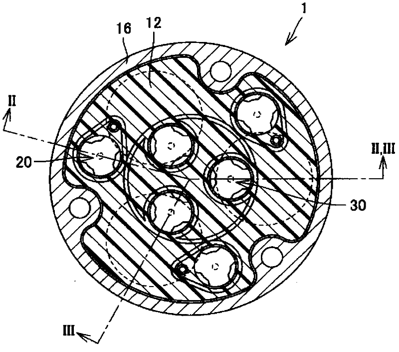
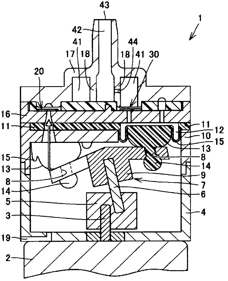
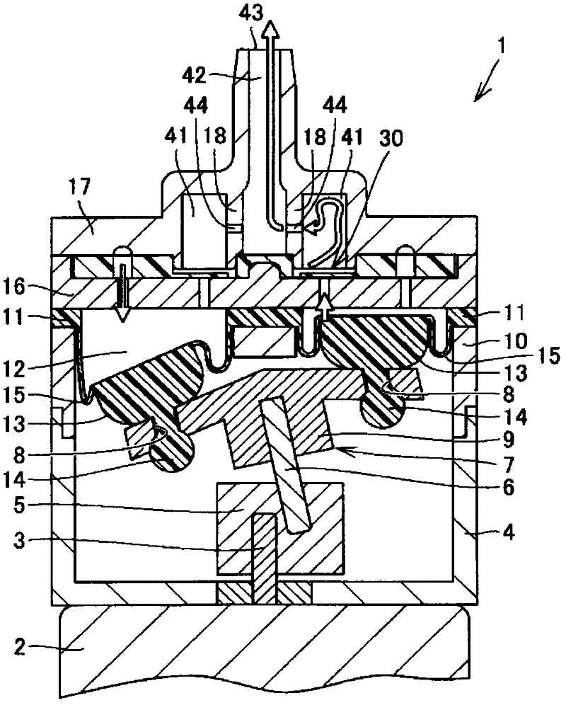
[0031] figure 1 It is a schematic plan view showing the structure of the diaphragm pump of the present invention. figure 2 is along figure 1 The sectional schematic diagram of the diaphragm pump shown in line II-II. image 3 is along figure 1 The sectional schematic diagram of the diaphragm pump of line II...


PUM


Abstract

Disclosed is a diaphragm pump that reduces pressure ripples in the discharged gas. This diaphragm pump (1) is a pump which transports a gas by means of volumetric changes in a pump chamber (12), and is equipped with: a discharge valve (30) that permits the flow of a gas which flows from the pump chamber (12), and prevents the flow of said gas in the opposite direction; an air chamber (41) into which flows gas that has been emitted from the pump chamber (12) through the discharge valve (30); a discharge port (43) that discharges the gas to the exterior of the diaphragm pump (1); and a through-hole part (44) that restricts the flow volume of the gas that flows from the air chamber (41) to the discharge port (43).

Description

technical field [0001] The invention relates to a diaphragm pump and a sphygmomanometer. Background technique [0002] In recent years, more and more attention has been paid to the self-management of blood pressure, which has led to the widespread use of home blood pressure monitors. When measuring blood pressure, an armband with a built-in air bag is wrapped around a part of the body, and the air bag is filled with air to increase the pressure. Blood pressure is measured based on the arterial information obtained by compressing the body. An air pump is used to pressurize the air bag. The air pump includes a rubber-like diaphragm forming a pump chamber in a casing, a piston provided on the diaphragm, and a driver attached to the piston. The driving body swings to reciprocate the piston, thereby changing the volume in the pump chamber. The pump function of conveying air is exerted by the volume change of the pump chamber. In order to prevent the discharged air and the su...

Claims


Application Information

Patent Timeline
Patent Type & Authority Applications(China)
IPC IPC(8): F04B45/04A61B5/022
CPCA61B5/0235A61B5/02141A61B5/02233A61B5/0225F04B43/026F04B1/148A61B2560/04
Inventor 佐野佳彦茎田知宏
Owner OMRON HEALTHCARE CO LTD
Why Eureka
Eureka Blog
Learn More