
A power quality conditioner for electrified railway

A technology of power quality and regulator, applied in the direction of transformer/inductor coil/winding/connection, reactive power adjustment/elimination/compensation, AC network to reduce harmonic/ripple, etc., which can solve the limited effect of negative sequence compensation , Transformer complex process, too many windings and other problems, to achieve the effect of simple control, good harmonic current suppression characteristics and dynamic response characteristics, and improve control accuracy

Inactive Publication Date: 2011-12-21
CHINA ELECTRIC POWER RES INST +1
View PDF4 Cites 6 Cited by
  • Summary
  • Abstract
  • Description
  • Claims
  • Application Information

AI Technical Summary

Problems solved by technology

But the disadvantage of this method is: TCR itself also generates harmonics, and the compensation for negative sequence is limited
Since the rated voltage of the traction bus in the traction station is 27.5kV, and the AT power supply mode is 55kV, limited by the withstand voltage level of the current fully-controlled power devices, the chain-type structure converter directly connected to the traction network through the reactor will lead to If the 3300V grade IGBT devices that are currently more mature are used, the number of modules cascaded will reach 30 at the 27.5kV voltage level, and the number will more than double under the AT power supply mode, resulting in control problems. At the same time, it will also lead to too many windings of the large-capacity single-phase multi-winding transformer on the other side of the back-to-back, resulting in complex process, difficult design, and large footprint of the transformer, which is difficult in practical application.

Method used


Image

  • A power quality conditioner for electrified railway
  • A power quality conditioner for electrified railway

Examples


Embodiment Construction

[0021] The specific implementation manners of the present invention will be further described in detail below in conjunction with the accompanying drawings.

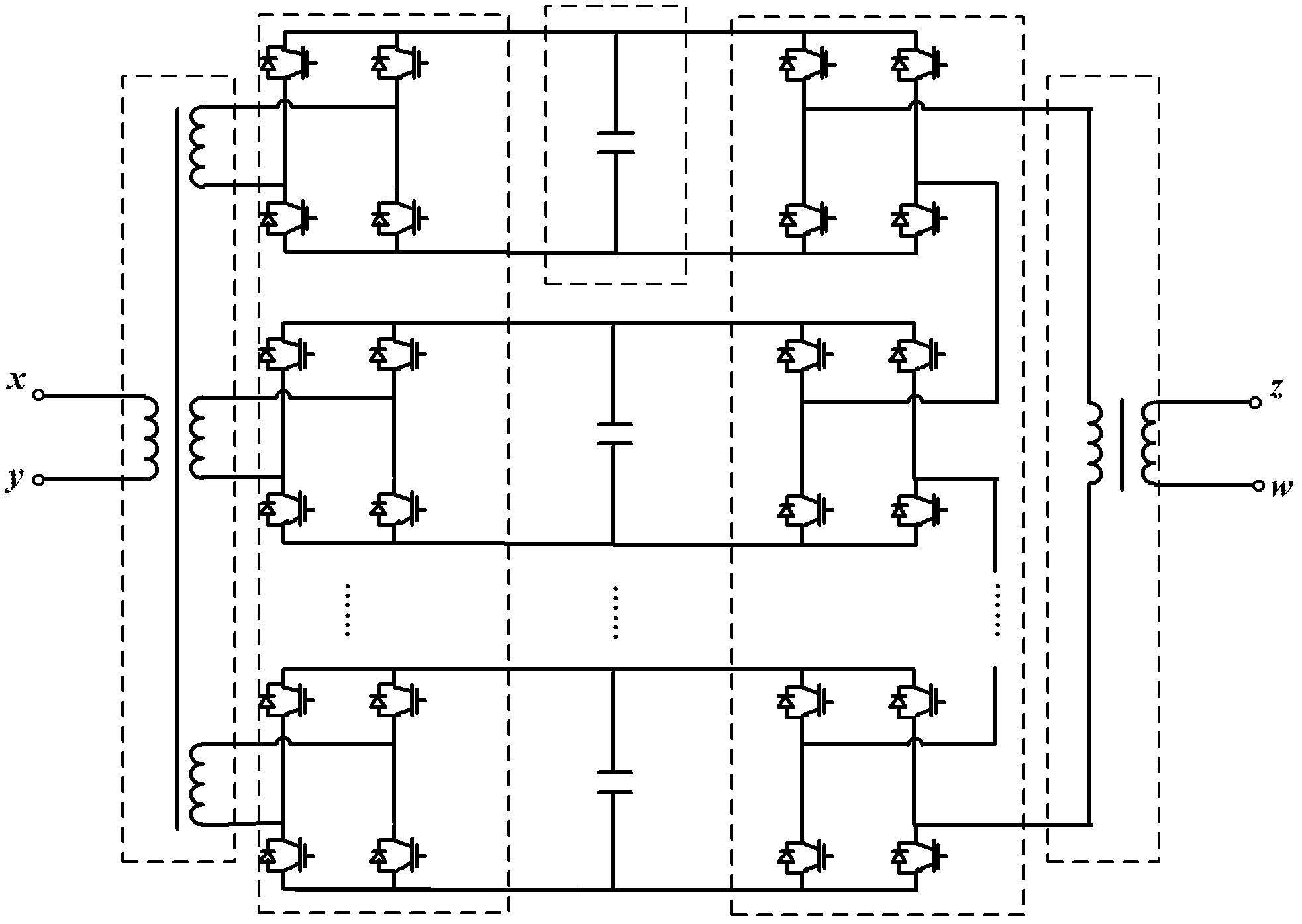
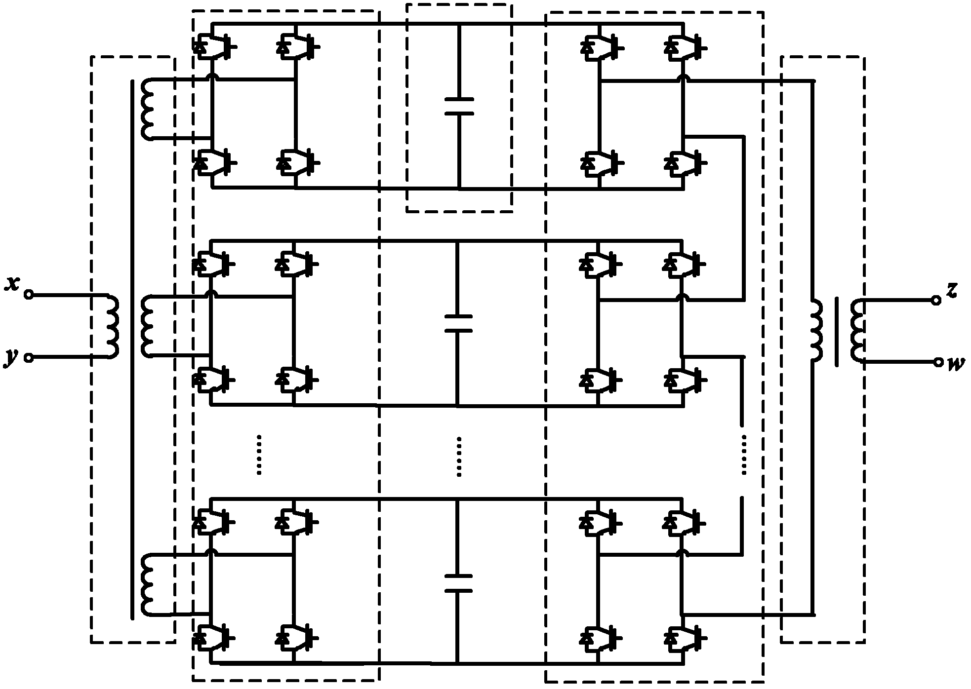
[0022] As shown in Figure 1, a kind of power quality conditioner of electrified railway comprises single-phase multi-winding transformer, single-phase single-winding transformer, converter (I, II) and capacitor;

[0023] The device of this embodiment uses a single-phase multi-winding transformer to realize the parallel connection and electrical isolation functions of multiple voltage source converters. The single-phase multi-winding transformer is composed of a primary winding and m secondary windings; the secondary windings are connected in parallel;

[0024] A single-phase single-winding transformer consists of a primary winding and a secondary winding;

[0025] Both converter I and converter II are voltage source converters, and each voltage source converter adopts a single-phase two-level H bridge arm structure, and...


PUM


Abstract

The present invention is a kind of electrified railway power quality conditioner, comprises single-phase multi-winding transformer, single-phase single-winding transformer, converter (I, II) and electric capacity; One end of the converter I is connected in series, the other end of the converter I is connected in parallel with the capacitor and then connected back to back with the converter II, and the converters II are connected in a chain structure and then connected in series with the single-phase single-winding primary winding. The present invention adopts a single-phase transformer and a chain structure, which can reduce switching loss, improve device operation efficiency and reliability, reduce the number of device links, reduce the complexity of device structure, improve control accuracy, and reduce the pulse output to the control system Synchronization requirements. The invention solves the problems of negative sequence, reactive power and harmonic exceeding standard in the traction station of the electric railway, and has the advantages of small occupied area of ​​the device, small loss, simple control, low cost and high reliability.

Description

Technical field: [0001] The invention relates to the fields of electrified railway power supply, power electronics technology and power quality control, in particular to an electrified railway power quality regulator. Background technique: [0002] The load of electrified railway has the characteristics of nonlinearity, asymmetry and fluctuation. On the one hand, since the electrified railway traction power supply system adopts single-phase power supply mode, and the electric locomotive is a single-phase load, no matter what wiring mode the traction transformer adopts, a large negative sequence current will be injected into the system; on the other hand, due to the The locomotive uses power electronic converters, so a large number of harmonics are injected into the system. In addition, because the load of the traction substation fluctuates at any time with the number of trains in the power supply arm and the operating status of each train, the load of electrified railways a...

Claims


Application Information

Patent Timeline
Patent Type & Authority Applications(China)
IPC IPC(8): H02M7/12H01F27/28H02J3/01H02J3/18
CPCY02E40/30Y02E40/40
Inventor 乔光尧刘颖英于坤山周胜军
Owner CHINA ELECTRIC POWER RES INST
Learn More