
Bilateral drive four-point force press

A bilateral drive and press technology, applied in the field of presses, to achieve the effects of prolonging service life, reducing deformation and reducing wear

Inactive Publication Date: 2011-12-21
JDM JINGDA MASCH (NINGBO) CO LTD
View PDF4 Cites 4 Cited by
  • Summary
  • Abstract
  • Description
  • Claims
  • Application Information

AI Technical Summary

Problems solved by technology

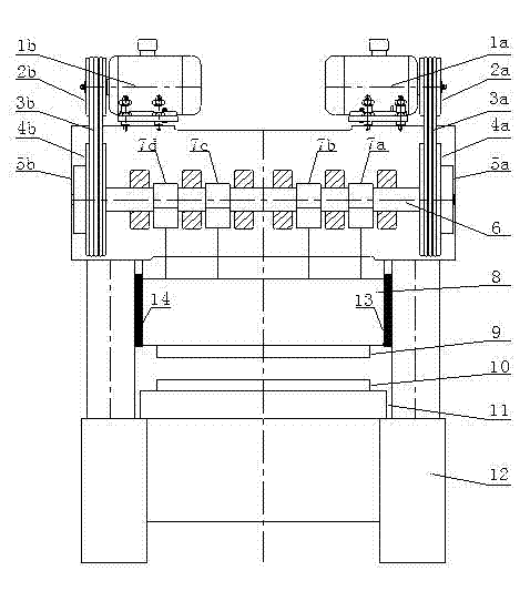
[0009] The technical problem to be solved by the present invention is to provide a bilaterally driven four-point force press in order to improve the defects of the above presses, which adopts two flywheels and two clutches installed on both sides of the main shaft respectively, and four eccentric force The force points are symmetrically arranged on both sides of the main shaft. Two motors located on both sides of the main shaft are used to drive the four force points on the main shaft at the same time, so that the slider can rise or fall at the same time without tilting, and while ensuring the light weight of the slider With high rigidity, reducing the deformation of the slider during stamping

Method used


Image

  • Bilateral drive four-point force press
  • Bilateral drive four-point force press
  • Bilateral drive four-point force press

Examples


Embodiment Construction

[0022] The present invention will be further described in detail below in conjunction with the accompanying drawings and embodiments.

[0023] Such as figure 1 The shown press includes a fuselage 12, a worktable 11 is installed in the fuselage 10, a lower mold 10 of the press mold is installed on the worktable 11, and four eccentric force application points 7a, 7b, 7c and 7d are respectively Installed on the main shaft 6, the slider 8 is connected to the main shaft 6 through four eccentric force application points 7a, 7b, 7c and 7d, and the upper mold 9 of the press mold is installed on the bottom plane of the slider 8, opposite to the lower mold 10, The machining of the workpiece between the upper die and the lower die is completed by the reciprocating motion of the slider between the upper dead center and the lower dead center.

[0024] The first motor 1a and the second motor 1b are installed on the top of the fuselage 12 respectively, and the two motor pulleys 2a and 2b a...


PUM


Abstract

Bilateral drive four-point force press, which includes: a main shaft, a first eccentric force application point, a second eccentric force application point, a third eccentric force application point, a fourth eccentric force application point, a driver, a first flywheel and a second flywheel, a second eccentric force application point, A clutch and a second clutch, the first eccentric force application point, the second eccentric force application point, the first flywheel and the first clutch are located on one side of the main shaft, the third eccentric force application point, the fourth eccentric force application point, the second flywheel and the second clutch Located on the other side of the main shaft, the driver drives two flywheels to rotate at the same time. The two flywheels drive a main shaft to rotate through the action of two clutches. Four eccentric force application points are installed on the main shaft, and the main shaft drives the slider through the action of four eccentric force application points. It moves up and down, thereby driving the upper mold of the press mold installed on the bottom plane of the slider to reciprocate up and down, and completes the processing of the workpiece between the upper mold and the lower mold. The movement precision, the bottom dead point precision, the guide precision and the precision of the workpiece processing of the slider are improved, and at the same time, it is beneficial to prolong the service life of the press machine and the mold.

Description

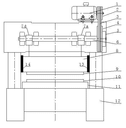
technical field [0001] The invention relates to a press, in particular to a press in which two motors drive a main shaft, and the main shaft drives a slider to move up and down through four force application points. Background technique [0002] Existing presses see figure 2 , generally includes: a main shaft 6, two eccentric force application points 7a and 7d, a flywheel 4, a clutch 5, and a motor 2, the flywheel, clutch and motor are located on one side of the main shaft, the motor drives the flywheel, and the main shaft is driven by the action of the clutch Rotate, the main shaft drives the slider 8 to move up and down through the action of two eccentric force application points, so that when the main shaft rotates, the distance between the action point of the clutch acting on the main shaft and the force application point 7a at the end of the press close to the flywheel is smaller than this action point to The distance between the application points 7d away from the end...

Claims


Application Information

Patent Timeline
IPC IPC(8): B30B1/26
Inventor 郑良才陈泉剑叶文聪
Owner JDM JINGDA MASCH (NINGBO) CO LTD
Learn More