
Adjustable Z-shaped offset bending mold

A bending mold, adjustable technology, applied in the field of sheet metal bending molds, can solve problems such as complex structure, lower production efficiency, and higher mold processing costs, and achieve the effects of reducing use costs, reducing processing time, and reducing processing costs

Inactive Publication Date: 2011-12-21
MAANSHAN CHENXING MACHINERY MFG
View PDF7 Cites 8 Cited by
  • Summary
  • Abstract
  • Description
  • Claims
  • Application Information

AI Technical Summary

Problems solved by technology

[0002] The sheet metal industry often encounters the bending of Z-shaped parts. The height (H value) and plate thickness (t) of this Z-shaped part often change. Therefore, different bending methods must be designed for different plate thicknesses and different heights. The bending mold not only increases the workload of the designer, but also because the mold cannot be used universally, the production cycle of the mold is long, which increases the production cost and reduces the production efficiency; and the current Z-shaped bending mold, due to the The direction of the pressure is inconsistent with the direction of the bending force of the Z-shaped part. There is an angle between the directions of the two forces. There is a lateral force during bending, which is easy to change the mold gap and make the dimension of the Z-shaped workpiece after bending unstable. At the same time, it is troublesome to adjust the gap between the upper and lower molds of the mold, and the material and precision requirements of the upper and lower molds are high, and the structure is complex, which brings difficulties to the mold processing and increases the processing cost of the mold

Method used


Image

  • Adjustable Z-shaped offset bending mold
  • Adjustable Z-shaped offset bending mold
  • Adjustable Z-shaped offset bending mold

Examples


Embodiment Construction

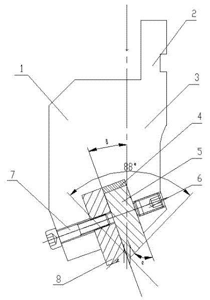
[0013] From Figure 1-Figure 3It can be seen from the figure that: an adjustable Z-shaped gap bending die is characterized in that: the adjustable Z-shaped gap bending die is mainly composed of an upper die 1 and a lower die 13, and the upper die 1 is mainly composed of an upper die Seat 3, upper fixed die 8, upper adjustable die 5, upper combined gasket 4, upper fixed bolt 7 and set screw 6, and lower die 13 is mainly composed of lower die base 14, lower fixed die 9, The lower adjustable die 10 and the lower fixing bolt 11 are composed. The upper mold base 3 is a long mold base with a cross-section that is arranged in the front and back directions and is a unequal rectangle. The upper part of the right side of the upper mold base 3 is vertically The cross-section of the device is rectangular and there is a clamping plate 2 with a rectangular long slot forward and backward. The plate 2 is a standard structure connecting the bending die and the machine tool slider plate, and c...


PUM

PropertyMeasurementUnit
Thicknessaaaaaaaaaa

Abstract

The invention discloses an adjustable Z-shaped offset bending mold and belongs to a sheet metal bending mold. The adjustable Z-shaped offset bending mold is characterized by mainly comprising an upper mold and a lower mold, wherein the upper mold mainly comprises an upper mold seat, an upper fixed press mold, an upper adjustable press mold, an upper combined gasket and an upper fixed bolt; the lower mold mainly comprises a lower mold seat, a lower fixed press mold, a lower adjustable press mold and a lower fixed bolt; the lower part of the upper mold seat is provided with a right-angled upperinclined through groove which forms a delta included angle with the pressure line of a bending machine; the upper inclined through groove is internally and correspondingly provided with the upper fixed press mold, the upper adjustable press mold and the upper combined gasket; the upper part of the lower mold seat is provided with a right-angled lower inclined through groove which also form a delta included angle with a vertical central line; the lower inclined through groove is internally and correspondingly provided with the lower fixed press mold, the lower adjustable press mold and the lower combined gasket; all the bottom surfaces or top surfaces of the upper fixed press mold, the lower fixed press mold, the upper adjustable press mold and the lower adjustable press mold are inclined surfaces which form theta included angles with the bottom surfaces or top surfaces of the upper mold seat and the lower mold seat correspondingly; and the upper mold and the lower mold are combined, and then the Z-shaped workpiece is formed. The adjustable Z-shaped offset bending mold has the advantages that the cost is low and the quality is good.

Description

technical field [0001] The invention belongs to a sheet metal bending die, in particular to a Z-shaped sheet metal bending die. Background technique [0002] The sheet metal industry often encounters the bending of Z-shaped parts. The height (H value) and plate thickness (t) of this Z-shaped part often change. Therefore, different bending methods must be designed for different plate thicknesses and different heights. The bending mold not only increases the workload of the designer, but also because the mold cannot be used universally, the production cycle of the mold is long, which increases the production cost and reduces the production efficiency; and the current Z-shaped bending mold, due to the The direction of the pressure is inconsistent with the direction of the bending force of the Z-shaped part. There is an angle between the directions of the two forces. There is a lateral force during bending, which is easy to change the gap between the molds and make the dimension...

Claims


Application Information

Patent Timeline
IPC IPC(8): B21D37/10
Inventor 陈淑玲程小平
Owner MAANSHAN CHENXING MACHINERY MFG
Learn More