
Punching die for car accelerator pedal bracket

A technology for accelerator pedals and automobiles. It is applied in the field of punching dies. It can solve problems such as failure to meet product size requirements, difficulty in ensuring hole concentricity, and increased production costs. It achieves easy replacement and processing, stable punching force, and extended service life. Effect

Inactive Publication Date: 2011-12-21
WUXI ZHONGJIE VIBRATION ISOLATORS
View PDF12 Cites 8 Cited by
  • Summary
  • Abstract
  • Description
  • Claims
  • Application Information

AI Technical Summary

Problems solved by technology

At present, there are two ways to process the concentric holes on both sides of the automobile accelerator pedal bracket: the first method is to punch the holes first and then bend them. Since the holes are processed first, the deformation of the material after bending makes the concentricity of the holes It is difficult to guarantee the degree of accuracy and cannot meet the product size requirements; the second method is to use the oblique wedge structure to punch holes on both sides at the same time, so that although the concentricity can be guaranteed, the die is very thin due to the product structure. The impact of the die is very easy to damage, and the die needs to be replaced frequently, which reduces the production efficiency and increases the production cost

Method used


Image

  • Punching die for car accelerator pedal bracket
  • Punching die for car accelerator pedal bracket
  • Punching die for car accelerator pedal bracket

Examples


Embodiment Construction

[0010] The specific embodiments of the present invention will be further described below in conjunction with the accompanying drawings.

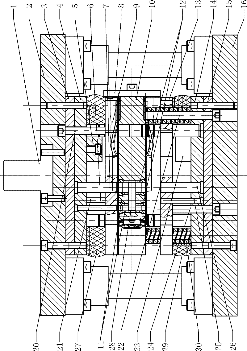
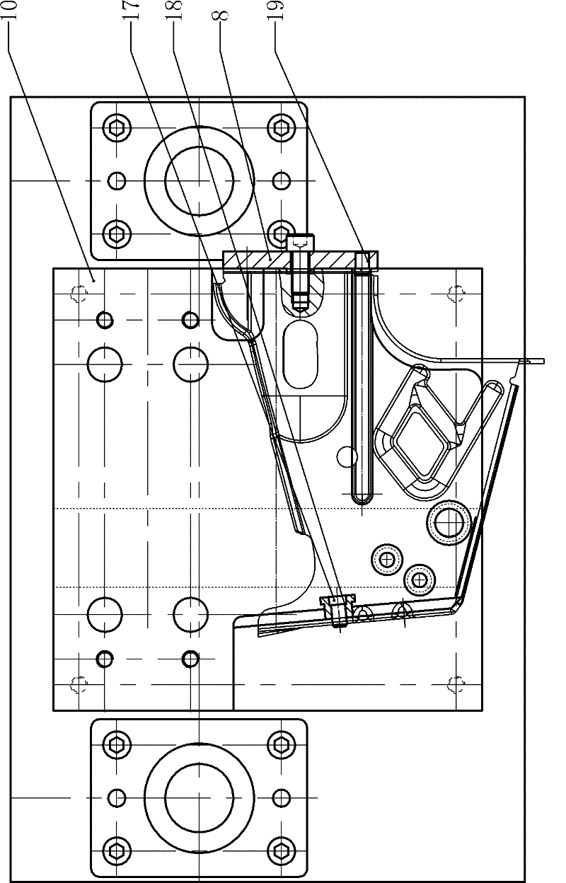
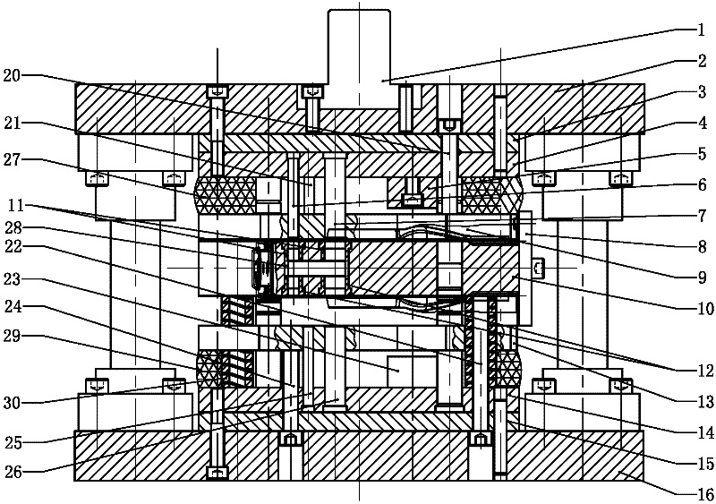
[0011] figure 1 , figure 2 , including die handle 1, upper template 2, upper backing plate 3, upper fixing plate 4, first limit column 5, upper punch 6, upper punch 7, side fixing plate 8, upper unloading plate 9, floating Die template 10, upper die insert 11, lower die insert 12, lower unloading plate 13, lower fixing plate 14, lower backing plate 15, lower formwork 16, positioning nail fixing plate 17, first positioning nail 18, The second positioning nail 19, the first post 20, the upper punch 21, the second post 22, the second limit post 23, the third post 24, the lower punch 25, the lower punch 26, and the upper unloading reset Rubber 27, material leakage hole 28, lower unloading reset rubber 29, back-moving spring 30 etc.

[0012] Such as figure 1 , figure 2 As shown, the present invention is a punching die for concentric holes ...


PUM


Abstract

The invention relates to a punching die for concentric holes on both sides of an automobile accelerator pedal bracket. An upper fixing plate is fixed under the upper template, an upper punch is fixed on the upper fixing plate, and a first post is slidably fitted on the upper fixing plate. An upper unloading plate is fixed at the lower end of a column, and an upper unloading reset rubber is arranged between the upper unloading plate and the upper fixing plate; a lower fixing plate is fixed on the lower template, and a lower punch is fixed on the lower fixing plate. The second post and the third post are slidingly fitted on the fixed plate, the upper end of the third post is fixed with a lower unloading plate, and a lower unloading reset rubber is arranged between the lower unloading plate and the lower fixing plate, and the second post The column passes through the lower unloading plate, the upper end of the second inserted column is fixed with a floating concave formwork, and a return spring is arranged between the floating concave formwork and the lower fixing plate. The invention adopts the floating concave template to process the concentric holes on both sides of the automobile accelerator pedal bracket, has stable punching force, prolongs the service life of the concave mold and reduces the cost of the mold.

Description

technical field [0001] The invention relates to a punching die, in particular to a punching die with concentric holes on both sides of an automobile accelerator pedal bracket. Background technique [0002] The small car accelerator pedal bracket is used for the installation of parts such as the accelerator pedal and the vehicle frame. If the concentricity of the concentric holes on both sides is out of tolerance during processing, it will directly affect the accuracy of the installation and the stability of the structure. At present, there are two ways to process the concentric holes on both sides of the automobile accelerator pedal bracket: the first method is to punch the holes first and then bend them. Since the holes are processed first, the deformation of the material after bending makes the concentricity of the holes It is difficult to guarantee the degree of accuracy and cannot meet the product size requirements; the second method is to use the oblique wedge structure...

Claims


Application Information

Patent Timeline
Patent Type & Authority Applications(China)
IPC IPC(8): B21D28/34
Inventor 魏忠尤佳
Owner WUXI ZHONGJIE VIBRATION ISOLATORS
Learn More