Vehicle cooling circuit with retarder or fluid coupling
A technology of cooling cycle and circulation loop, applied in hydraulic brakes, brake types, mechanical equipment, etc., can solve problems such as negative efficiency
- Summary
- Abstract
- Description
- Claims
- Application Information
AI Technical Summary
Problems solved by technology
Method used
Image
Examples
Embodiment Construction
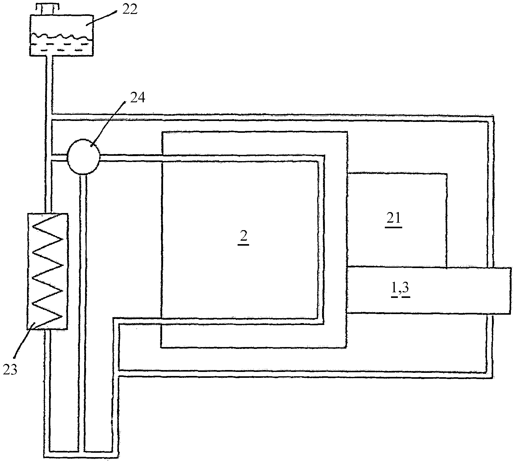
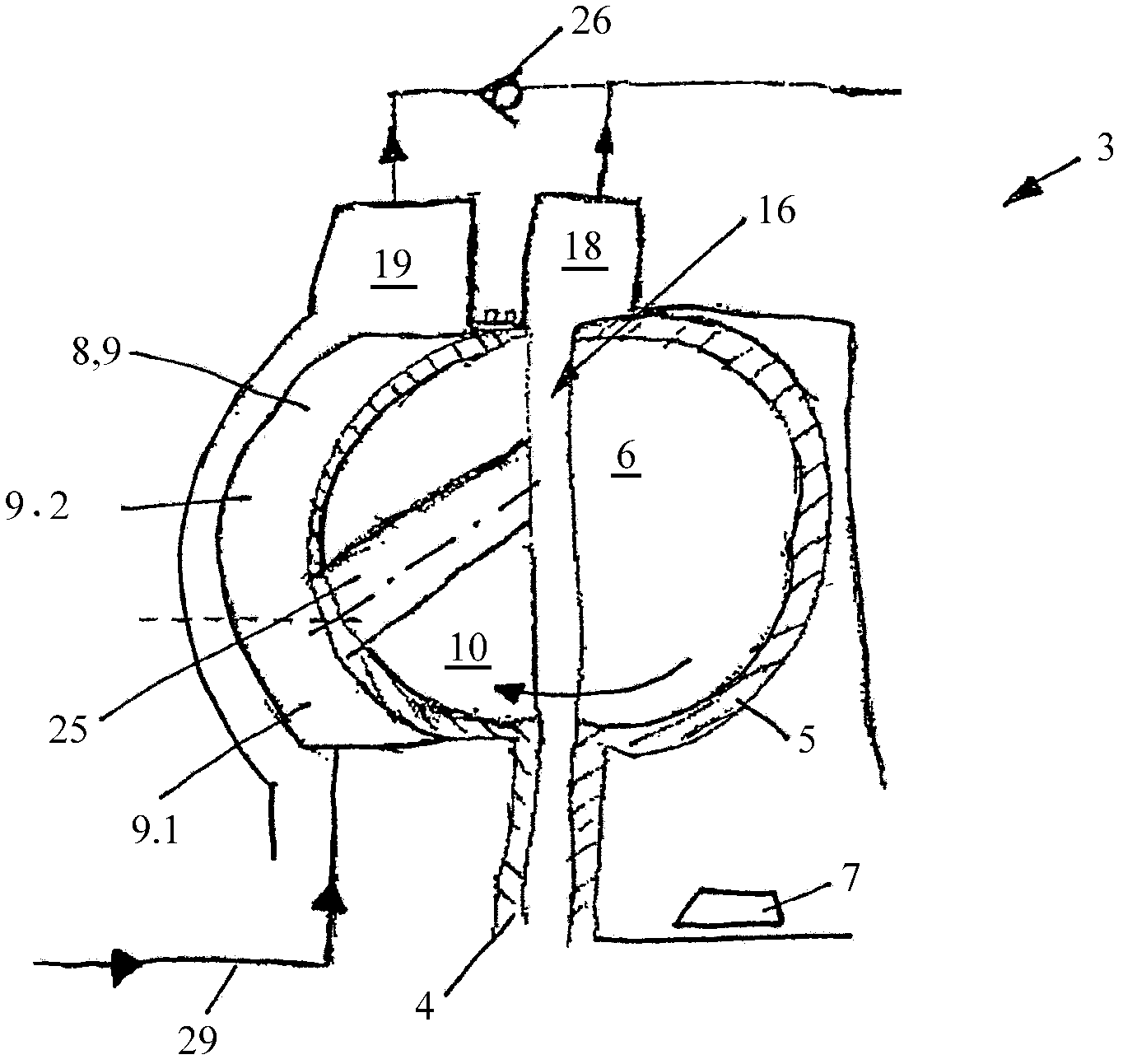
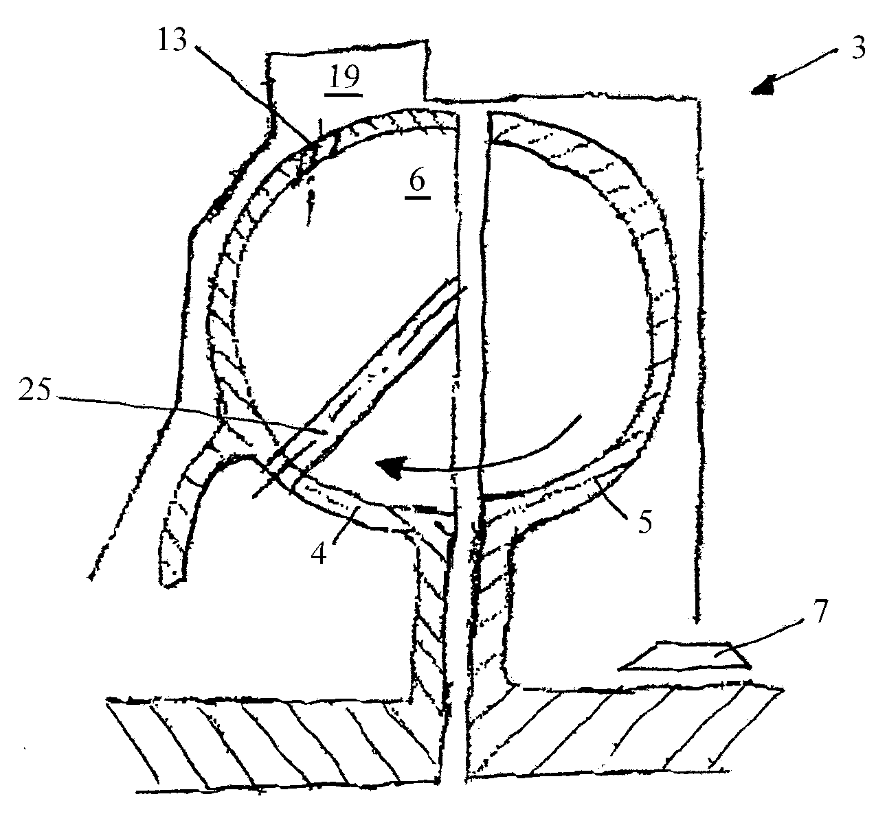
[0025] exist figure 1 A schematic diagram of a vehicle cooling circuit according to the invention is shown in . The vehicle drive engine 2 , the thermostat 24 and the heat exchanger 23 are connected in this order as viewed in the flow direction of the cooling medium. Furthermore, a compensation container 22 for the working medium is provided. In the cooling circuit, the hydrodynamic retarder 3 is in this case connected parallel to the vehicle drive engine 2 , the working medium of which is at the same time the cooling medium. The cooling medium can be water, oil or an aqueous mixture. Here, the hydrodynamic retarder 3 is designed as a primary retarder, that is to say it bypasses the transmission 21 or is coupled to the primary side of the transmission 21 during braking operation so that it can be designed, for example, directly as Vehicles with a diesel engine drive the drive shaft or crankshaft of the engine 2 to decelerate. An embodiment is also conceivable as a secondar...
PUM
 Abstract
Description
Claims
Application Information
 - R&D
- Intellectual Property
- Life Sciences
- Materials
- Tech Scout
- Unparalleled Data Quality
- Higher Quality Content
- 60% Fewer Hallucinations
Browse by: Latest US Patents, China's latest patents, Technical Efficacy Thesaurus, Application Domain, Technology Topic, Popular Technical Reports.
© 2025 PatSnap. All rights reserved.Legal|Privacy policy|Modern Slavery Act Transparency Statement|Sitemap|About US| Contact US: help@patsnap.com


