
A kind of LED backlight driving method, LED backlight driving circuit and liquid crystal display device

A technology for a backlight driving circuit and a liquid crystal display device, which is applied to lighting devices, electroluminescent light sources, light sources, etc., can solve problems such as loss, backlight brightness decline, and decline.

Inactive Publication Date: 2011-12-14
TCL CHINA STAR OPTOELECTRONICS TECH CO LTD
View PDF8 Cites 16 Cited by
  • Summary
  • Abstract
  • Description
  • Claims
  • Application Information

AI Technical Summary

Problems solved by technology

The disadvantage of this method is that when the temperature of the LED rises, its cross voltage (voltage across the LED) drops, the light intensity drops, and the brightness of the backlight also drops.
In addition, the detection of the minimum voltage causes the voltage difference between LED strings to be added to the constant current control circuit, causing unnecessary loss

Method used


Image

  • A kind of LED backlight driving method, LED backlight driving circuit and liquid crystal display device
  • A kind of LED backlight driving method, LED backlight driving circuit and liquid crystal display device
  • A kind of LED backlight driving method, LED backlight driving circuit and liquid crystal display device

Examples


Embodiment Construction

[0030] The present invention will be further described below in conjunction with the accompanying drawings and preferred embodiments.

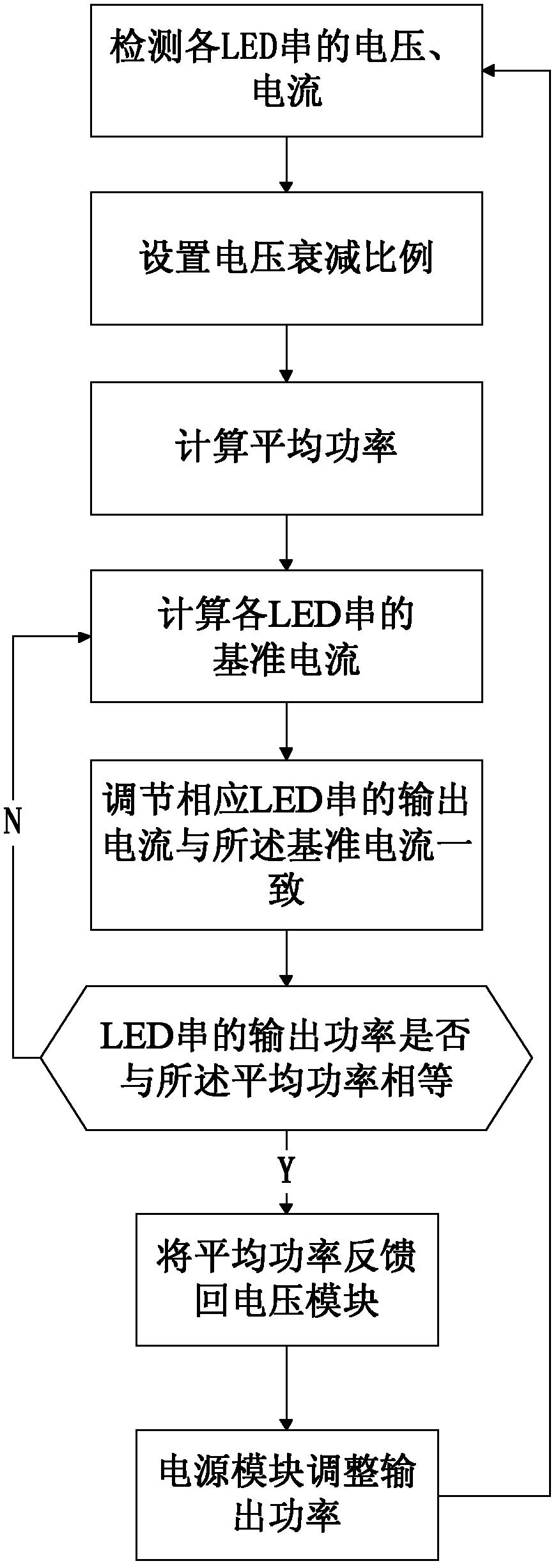
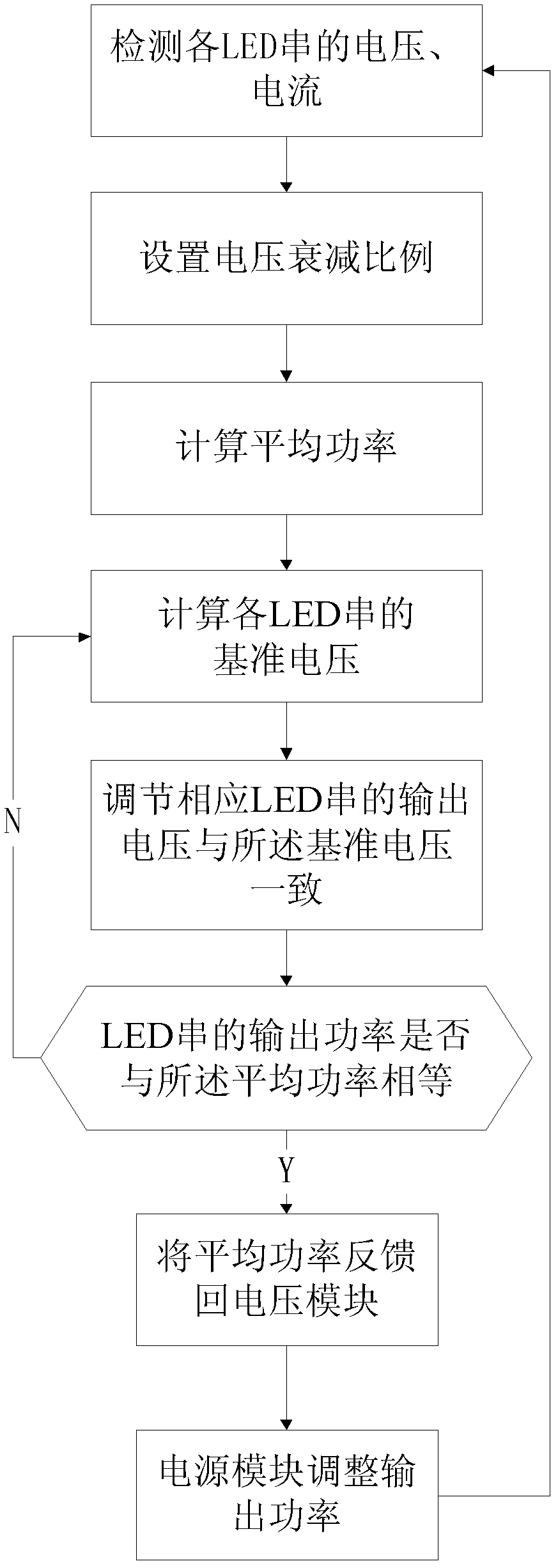
[0031] The inventive principle of the LED backlight driving method of the present invention is: by simultaneously detecting the cross-voltage and current of the Lightbar, setting the voltage attenuation ratio, and feeding back the product of the voltage Vf and the current If of the LED string, that is, Vf*If, if Vf is small , If will be large, and if If is large, Vf will also become large, and finally it will be compromised, so that the smaller Vf will move closer to the larger Vf; vice versa, the larger Vf will move closer to the smaller Vf. Finally, the voltage across the LED is very close. This can reduce the voltage applied to the current balance caused by the difference in the cross-voltage Vf.

[0032] When the temperature rises, the brightness of the backlight will decrease, and the Vf of the LED will decrease, and the If will increase...


PUM


Abstract

Disclosed are an LED backlight driving method, an LED backlight driving circuit, and a liquid crystal display device. The LED backlight driving method comprises the following steps: detecting the voltage and current of each LED string, calculating the power of each LED string, determining a reference power; and adjusting for each LED string the output power thereof until same equals the reference power. The constant power control scheme employed in the present invention, on the one hand, supplements a reduction in brightness of the LED due to heating, while on the other hand, by adjusting automatically the voltage and current of a light guide plate, thus allowing for reduced current for high crossover voltage, and for increased voltage for low crossover voltage, reduces the wearing and temperature of a constant current control circuit due to different crossover voltages.

Description

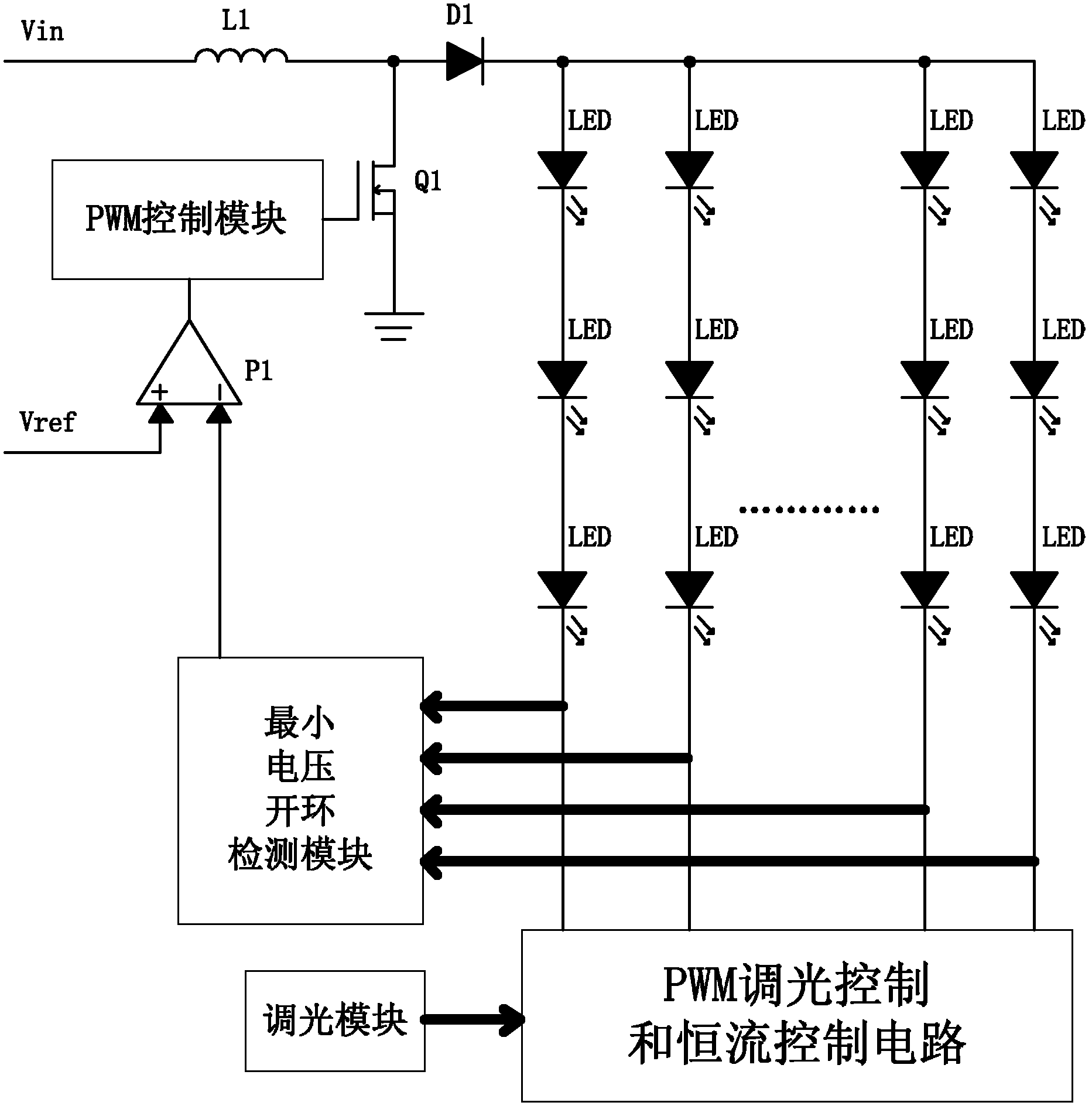
technical field [0001] The invention relates to the field of liquid crystal display, and more specifically relates to an LED backlight driving method, an LED backlight driving circuit and a liquid crystal display device. Background technique [0002] At present, LEDs are generally used as backlight sources for liquid crystal displays, and the existing LED drivers use such as figure 1 In the shown constant current driving mode, the constant current control circuit controls the LED current of each string to be constant; the minimum voltage is detected by the minimum voltage open-loop detection module to optimize the input voltage of the LED. The disadvantage of this method is that when the temperature of the LED rises, its cross voltage (voltage across the LED) decreases, the light intensity decreases, and the brightness of the backlight also decreases. In addition, detecting the minimum voltage causes the voltage difference between LED strings to be added to the constant cur...

Claims


Application Information

Patent Timeline
IPC IPC(8): G09G3/34G09G3/36
CPCY02B20/347H05B33/0818G09G3/3406H05B33/0827G09G2330/02G09G2320/041H05B45/38H05B45/46Y02B20/30
Inventor 高新明
Owner TCL CHINA STAR OPTOELECTRONICS TECH CO LTD
Learn More