TPU light conveyor belt for printing and dyeing industry and manufacturing method thereof

A light conveyor belt, industry-leading technology, applied in the field of conveyor belt manufacturing, can solve problems such as fiber length elongation, running length, belt surface damage, etc.

Inactive Publication Date: 2011-12-14
SHANGHAI YONGLI BELTING +1
View PDF8 Cites 19 Cited by
  • Summary
  • Abstract
  • Description
  • Claims
  • Application Information

AI Technical Summary

Problems solved by technology

[0003] The traditional printing and dyeing guide belt in the market is made of two layers of polyester filament fabric covered with TPU material, but this type of conveyor belt can no longer meet the requirements of high-performance printing products
During the use of this conveyor belt, as time goes by, there will be a "phenomenon" of running long. The reason is that the conveyor belt is pre-tensioned so that the length of the macromolecular chain bonds in the skeleton fibers increases and the bond angles open and close, resulting in The length of the fiber is elongated, showing creep and relaxation. During the printing process, the pattern cannot be aligned with high precision, resulting in misalignment and deformation of the pattern.
Moreover, the surface of the printing and dyeing conveyor belt produced by the traditional process is not resistant to solvents. During the cleaning process, the belt surface is easily corroded by solvents, resulting in damage and unevenness.
Another disadvantage of the traditional printing and dyeing conveyor belt is that the powder coating process is adopted, and the powder material cannot reach the state of dense surface layer during the process of coating heating and melting

Method used


Image

  • TPU light conveyor belt for printing and dyeing industry and manufacturing method thereof
  • TPU light conveyor belt for printing and dyeing industry and manufacturing method thereof
  • TPU light conveyor belt for printing and dyeing industry and manufacturing method thereof

Examples


Embodiment Construction

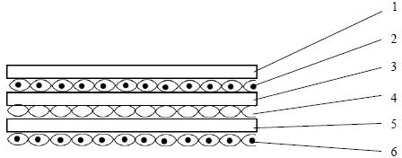
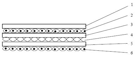
[0030] figure 1 As shown in the structural diagram of the TPU conveyor belt for the printing and dyeing industry, the TPU light conveyor belt for the printing and dyeing industry includes three layers of reinforced skeleton, one layer of covering surface layer and two layers of covering and bonding layer, wherein the first and third layers of reinforced skeleton adopt Polyester woven fabric, the warp direction yarn adopts ultra-low shrinkage polyester filament with a linear density of 1000D, the density is 52-58 threads / inch, and the weft direction adopts 0.25mm ultra-low shrinkage polyester monofilament, the density is 20-25 root / inch; the second layer of reinforced skeleton adopts Kevlar fiber woven fabric, the warp direction yarn adopts Kevlar filament with a linear density of 1000D, and the density is 20-25 strands / inch, and the weft direction adopts a linear density of 3 strands of 21S polyester short The density is 10-15 strands / inch; the covering layer is made of black ...


PUM

PropertyMeasurementUnit
Linear densityaaaaaaaaaa

Abstract

The invention relates to a TPU light-duty conveyor belt used in the printing and dyeing industry and a manufacturing method thereof. The fabric carrier is a three-layer reinforced skeleton, wherein the first and third layer reinforced skeletons are polyester woven fabrics, and the warp yarns are super Low-shrinkage polyester filament, 0.25mm ultra-low-shrinkage polyester monofilament is used in the weft direction, and the second layer of reinforced skeleton is made of Kevlar fiber woven fabric. 3 strands of 21S polyester staple fiber; the cover is made of black TPU polyester material with excellent solvent resistance. The advantages are: the light conveyor belt with this structure not only greatly improves the 1% elongation force, but also has a light body and good flatness, and at the same time achieves high strength and high alignment accuracy; the solvent-resistant TPU surface can be widely used with various cleaning agents, And it can be exposed to acetone and other similar solvents for a short time; the extrusion and calendering process is used to produce the TPU covering layer, which can ensure the compactness of the surface material of the light conveyor belt.

Description

technical field [0001] The invention relates to a TPU light conveyor belt used in the printing and dyeing industry, and also relates to a manufacturing method of the conveyor belt. Background technique [0002] In recent years, with the technological innovation of the textile printing and dyeing industry, the continuous adoption of new technologies and new raw materials has made the printing and dyeing industry develop rapidly. Its printing products are not only green and environmentally friendly, but also bright in color and high in precision. This puts forward higher requirements for the production equipment in the printing and dyeing industry. Take the printing guide belt as an example: the printing guide belt is a light conveyor belt with high precision requirements. The tape is required to be resistant to detergents and dyes, to have distinct colors on the pattern, to have clear and orderly outlines, and to have high precision for pattern alignment. It is widely used i...

Claims


Application Information

Patent Timeline
IPC IPC(8): B41F15/14B32B27/08B32B27/12B32B27/40B32B27/36
Inventor 陆晓理兰竹史佩浩
Owner SHANGHAI YONGLI BELTING
Why Eureka
Try Eureka