
Blade Mounting Device for Reciprocating Cutting Tools

A technology for installing devices and cutting tools, which is applied in the direction of sawing machine devices, manufacturing tools, metal sawing equipment, etc., can solve the problems of unstable position of saw blade 33, unstable reciprocating motion, etc., and achieve improved alignment effect and smooth reciprocating motion action, the effect of reducing the size of the structure

Active Publication Date: 2011-12-14
MAKITA CORP
View PDF6 Cites 8 Cited by
  • Summary
  • Abstract
  • Description
  • Claims
  • Application Information

AI Technical Summary

Problems solved by technology

[0008] Therefore, as shown in the figure, when the head 33a of the flat plate-shaped saw blade 33 and the plate-shaped saw blade guide member 32 are pressed in a cross shape, the direction of the blank arrow in the figure (the width direction of the saw blade 33) As shown, in fact, the head 33a of the saw blade 33 tends to deviate from the guide groove 32b of the saw blade guide member 32 in the above-mentioned direction, which will cause the position (installation position) of the saw blade 33 to be unstable, thereby causing its reciprocating movement. Unsteady movements

Method used


Image

  • Blade Mounting Device for Reciprocating Cutting Tools
  • Blade Mounting Device for Reciprocating Cutting Tools
  • Blade Mounting Device for Reciprocating Cutting Tools

Examples


Embodiment Construction

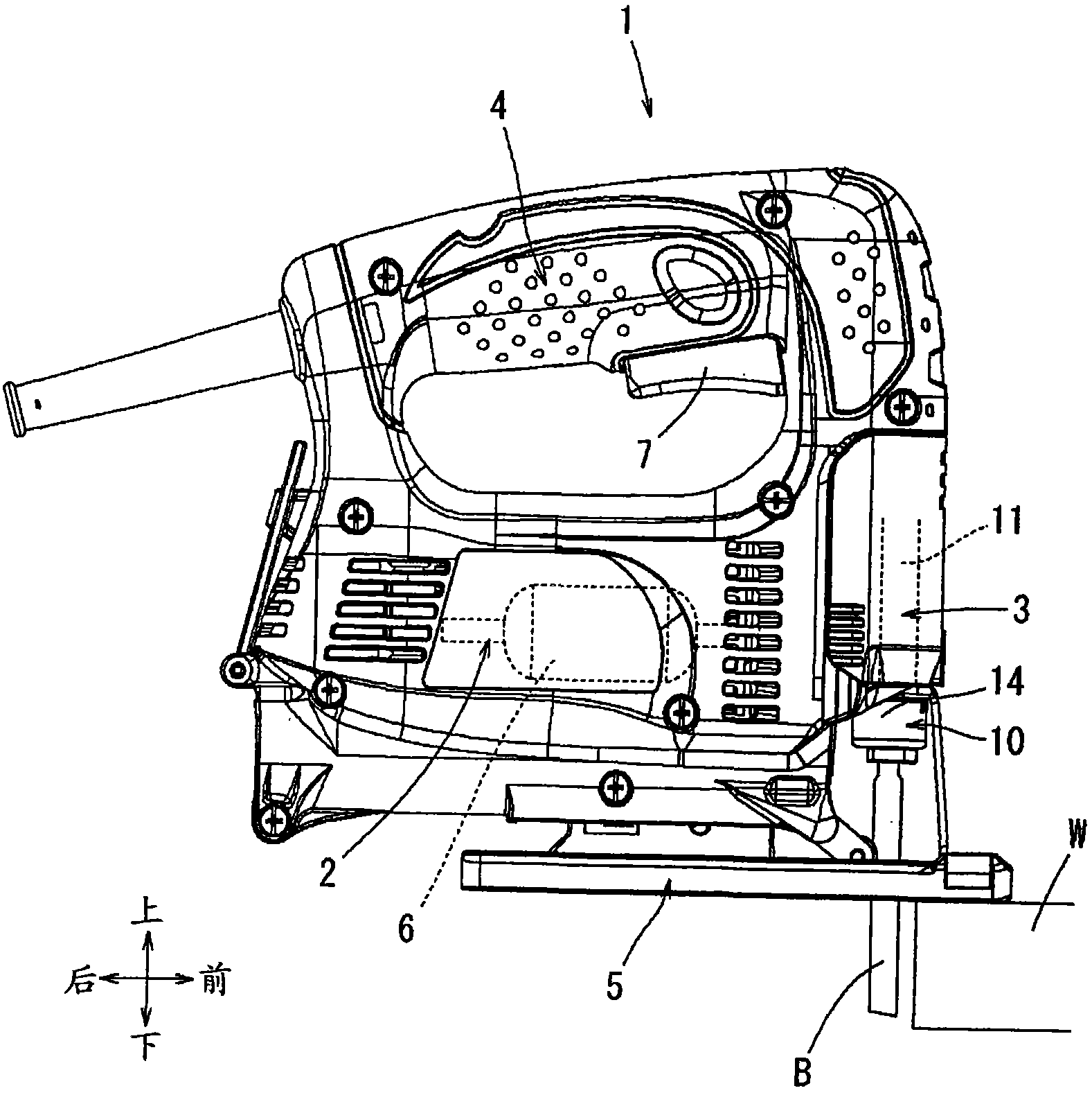
[0034] The following is based on Figure 1 to Figure 17 Embodiments in the present invention will be described. In this embodiment, the jigsaw 1 is illustrated as an example of a reciprocating cutting tool. figure 1 It is a figure which shows the overall appearance shape of this jigsaw 1. The jigsaw 1 includes: a tool body 2 in which a motor 6 is accommodated; and a base 5 supported on the lower surface of the tool body 2 in an extended state. The upper part of the tool body part 2 is provided with an annular handle part 4 for the user to hold, and the front part of the tool body part 2 is housed with a reciprocating motion conversion mechanism 3 .

[0035] exist figure 1 , the user is located on the left side of the jigsaw 1 . When the user moves the jigsaw 1 forward while holding the handle 4 and positioning the base 5 on the upper surface of the material W to be cut, the saw blade B can cut into the material W to be cut to perform cutting work.

[0036] A switch oper...


PUM


Abstract

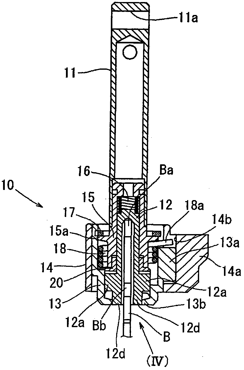
A blade mounting device (10) of a cutting tool (1) includes a lock device (13, 14) and a blade guide (12). The lock device (13, 14) is configured to releasably lock a blade (B) against a rod (11) of a cutting tool (1). The blade guide (12) is movable relative to the rod (11) in an axial direction of the rod (11) and is coupled to the lock device (13, 14), so that the lock device (13, 14) locks and releases the blade (B) in response to position of the blade guide (12) in the axial direction. The blade guide (12) has a guide recess (12c) capable of guiding and engaging the blade (B), so that the blade guide (12) can be moved by the blade (B) in the axial direction through engagement of the guide recess (12c) with the blade (B). The blade guide (12) has a configuration other than a thin flat plate configuration.

Description

technical field [0001] The invention relates to a saw blade (saw blade) mounting device for a reciprocating cutting tool, wherein the reciprocating cutting tool is, for example, a portable cutting tool called a jigsaw, and a flat plate-shaped Saw blade (saw blade). Background technique [0002] As a jigsaw, the rotation of the motor housed in the jigsaw is converted into reciprocating motion by a reciprocating motion converting mechanism. The reciprocating rod is provided with a saw blade installation device for installing a flat plate-like saw blade. For this saw blade mounting device, in the prior art, in order to adopt one-touch operation and just can load on or take off saw blade, people have figured out various methods. In the following patent documents, there is disclosed a prior art related to a saw blade mounting device. [0003] The saw blade installation device in the above-mentioned prior art has: an operating part, which is in the form of a ring, and when it i...

Claims


Application Information

Patent Timeline
Patent Type & Authority Applications(China)
IPC IPC(8): B23D51/10
CPCB23D51/10
Inventor 可儿利之山村刚
Owner MAKITA CORP
Learn More