Novel paraffin injection valve of paraffin continuous molding machine

A molding machine and wax injection technology, which is applied to valve details, multi-way valves, valve devices, etc., can solve the problems of waste of raw materials, many processes, and large space occupation, so as to ensure the accuracy of wax injection, avoid jet splashing, and slow down the flow rate Effect

Active Publication Date: 2013-06-05
大连天禄机电设备制造有限公司
View PDF4 Cites 0 Cited by
  • Summary
  • Abstract
  • Description
  • Claims
  • Application Information

AI Technical Summary

Problems solved by technology

Its disadvantages are: ① complex process, many procedures, and long manufacturing cycle; ② large volume, large material consumption, and large space occupation; ③ heavy weight, and it is installed on the bottom of the trough, which is extremely inconvenient for maintenance and replacement; ④ Two kinds of power are required to be controlled separately during work, and the external power system is complicated; ⑤ Due to the mechanical interlocking transmission, the timing and quantitative wax injection time is limited, and it takes 10 seconds to inject 5 kg of liquid wax, so the efficiency is low; ⑥ Because the outlet flow channel is straight-through There is no buffer space, and the flow rate is faster under the same pressure. When it is injected into the wax plate, it will form a reflection and splash in the form of mist, which not only affects the accuracy of wax injection, but also causes waste of raw materials and pollutes the environment.

Method used


Image

  • Novel paraffin injection valve of paraffin continuous molding machine
  • Novel paraffin injection valve of paraffin continuous molding machine

Examples


Embodiment Construction

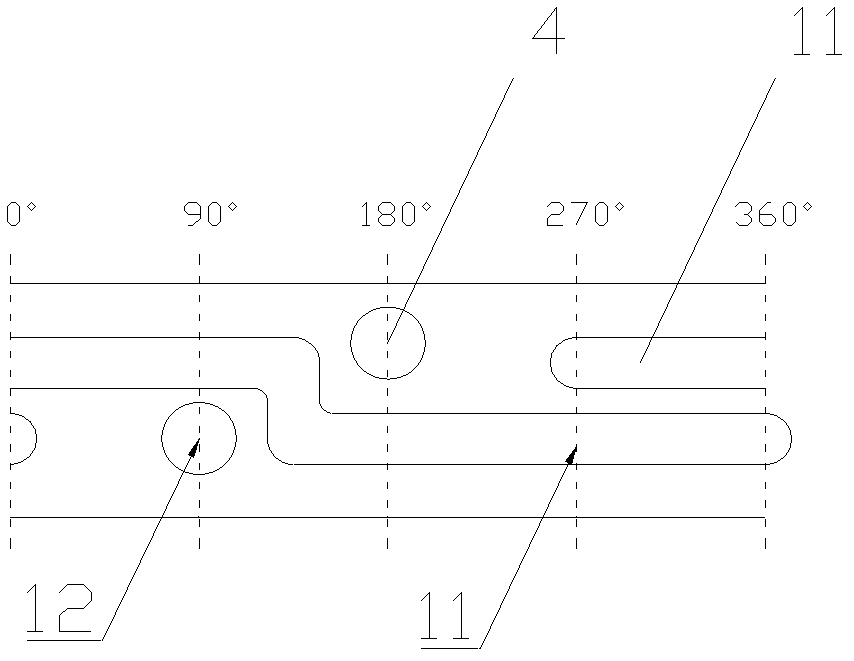
[0019] Such as figure 1 As shown, the wax injection valve is composed of a cylinder 1, a valve stem 2, a valve body 3, a valve core 5 and a valve seat 7. The cylinder 1 is connected to the upper end of the valve stem 2, and the valve stem 2 is a rod-shaped body processed by 304 stainless steel. , the lower end of the valve stem 2 is in the lower part of the valve body 3, the end is inlaid with a valve core 5, and the middle part of the valve core 5 is provided with an opening groove 6, mainly to reduce the weight of the valve core 5; through the up and down movement of the valve core 5, the valve The inlet 12 of the body 3 is either communicated with the outlet 8 or communicated with the return port 4; the lower end of the valve body 3 is processed to form a valve seat 7.

[0020] The valve body 3 is a cylindrical three-way valve body of φ100mm×100mm processed by ordinary 304 stainless steel. The side surface corresponding to the upper part of the valve body 3 forms an angle ...


PUM


Abstract

The invention aims to provide a novel paraffin injection valve of a paraffin continuous molding machine and solves the problem in the existing paraffin injection valve. The paraffin injection valve provided by the invention is composed of a cylinder, a valve rod, a valve body, a valve core and a valve seat, wherein the valve body is a cylindrical three-way valve body, the lower end of the valve body is processed to form the valve seat; an entrance and a reflux inlet of the three-way valve body are distributed on the side corresponding to the middle-upper part of the cylindrical valve body andform a 90-degree angle along the circumference, the entrance is arranged on the side of the middle-lower part; the entrance is connected with a feeding pipe orifice wire, the reflux inlet is connected with a reflux pipeline wire, an exit is arranged on the lower end of the valve seat and forms a bell mouth shape that is narrower at the top and wider at the bottom; the cylinder is connected with the upper end of the valve rod, the lower end of the valve rod is arranged on the lower part in the valve body, and the end part is lined with the valve core; and when the paraffin injection valve works, the paraffin injection valve is opened or closed by the valve core. The paraffin injection valve provided by the invention has the following advantages: the structure is simple and reasonable, the volume is small and the weight is light; pipelines are connected in a straight line, thus the efficiency is high; sputtering can be avoided, energy conservation and environmental protection can be realized, paraffin injection precision is high; and the outer layer of the valve body is provided with a heating device, so that the temperature of liquid paraffin can be adjusted.

Description

technical field [0001] The invention relates to a wax injection device for a continuous paraffin molding machine, in particular to a novel wax injection valve for a continuous paraffin molding machine. Background technique [0002] The existing paraffin continuous molding machine uses a three-way rotary switching valve, and its structure is basically: the valve body is a cuboid made of alloy steel, and the size after processing is 410mm×195mm×96mm, and it is fixed on the bottom of the trough; The valve stem is installed longitudinally through the valve body, which can be directly controlled by pneumatics and indirectly controlled by electrics. Two half-through and one full-through oval holes are processed in sequence on the valve body, which are respectively material inlets; when the liquid wax cylinder When the piston is lifted, the valve stem rotates by linkage action. When the liquid wax in the liquid wax cylinder reaches the limit, the valve stem rotates 45° to close the...

Claims


Application Information

Patent Timeline
Patent Type & Authority Patents(China)
IPC IPC(8): F16K11/044F16K27/02B29C39/24
Inventor 于永成于永强张运鑫
Owner 大连天禄机电设备制造有限公司
Why Eureka
Try Eureka