Positive and negative pressure combined delivery tank

A combined type and tank-transporting technology, which is applied in the direction of conveyors, conveying bulk materials, transportation and packaging, etc., can solve the problems of time-consuming, labor-intensive, environmental pollution, low efficiency, etc., and achieve advanced technology, high degree of installation freedom, and reasonable structure Effect

Inactive Publication Date: 2011-12-07
季胜
View PDF10 Cites 5 Cited by
  • Summary
  • Abstract
  • Description
  • Claims
  • Application Information

AI Technical Summary

Problems solved by technology

[0002] Traditional material transportation often adopts manual handling or conveyor belt transportation, which has low efficiency, and dust particles generated during transportation are likely to cause environmental pollution
[0003] Existing material sending tanks often adopt positive pressure conveying and feeding, and have certain requirements on the space height, because they must be fed by the gravity of the material, that is, the material needs to be transported to the feeding port on the top of the sending tank by manual handling ,Time-consuming

Method used


Image

  • Positive and negative pressure combined delivery tank
  • Positive and negative pressure combined delivery tank

Examples


Embodiment Construction

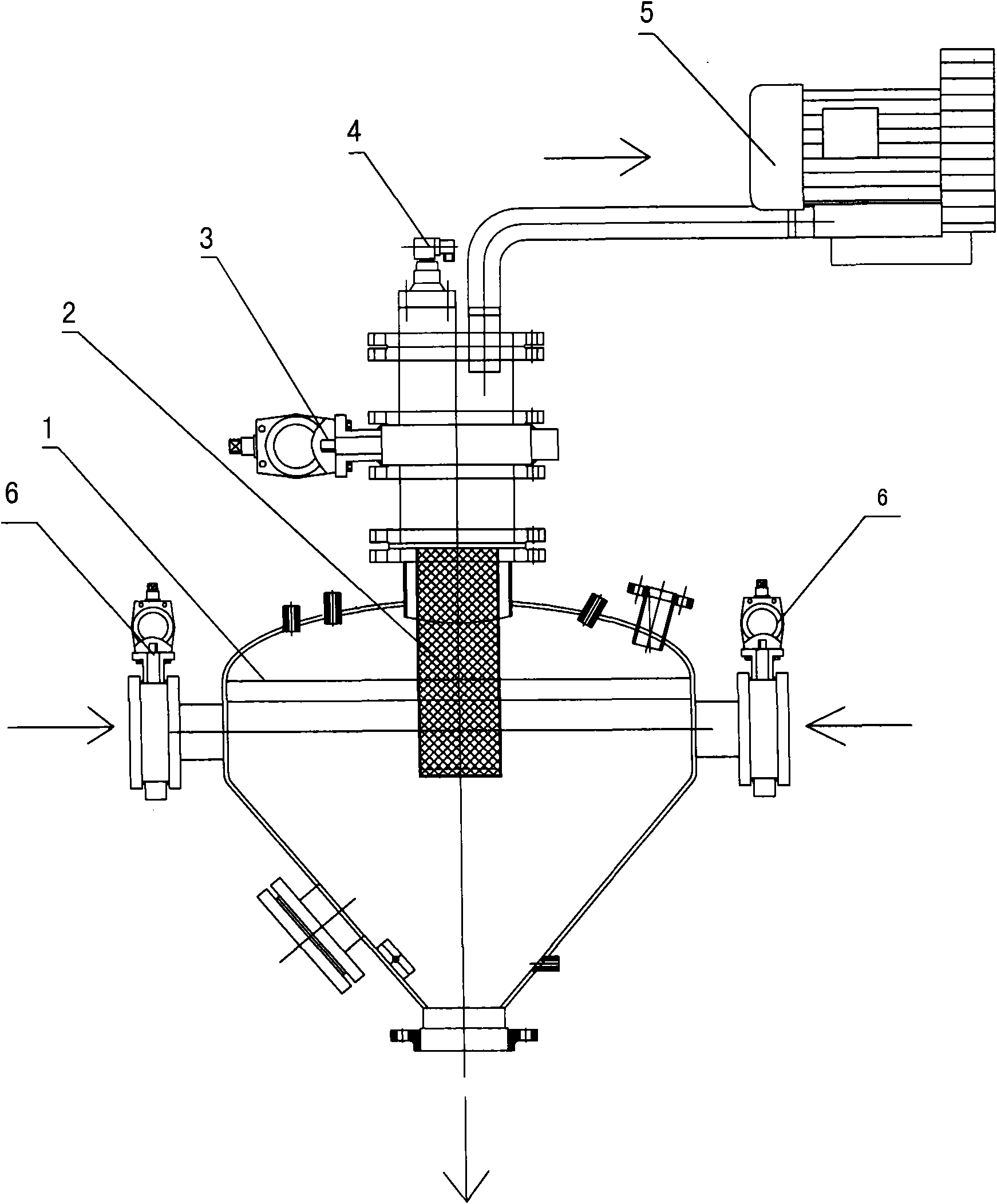
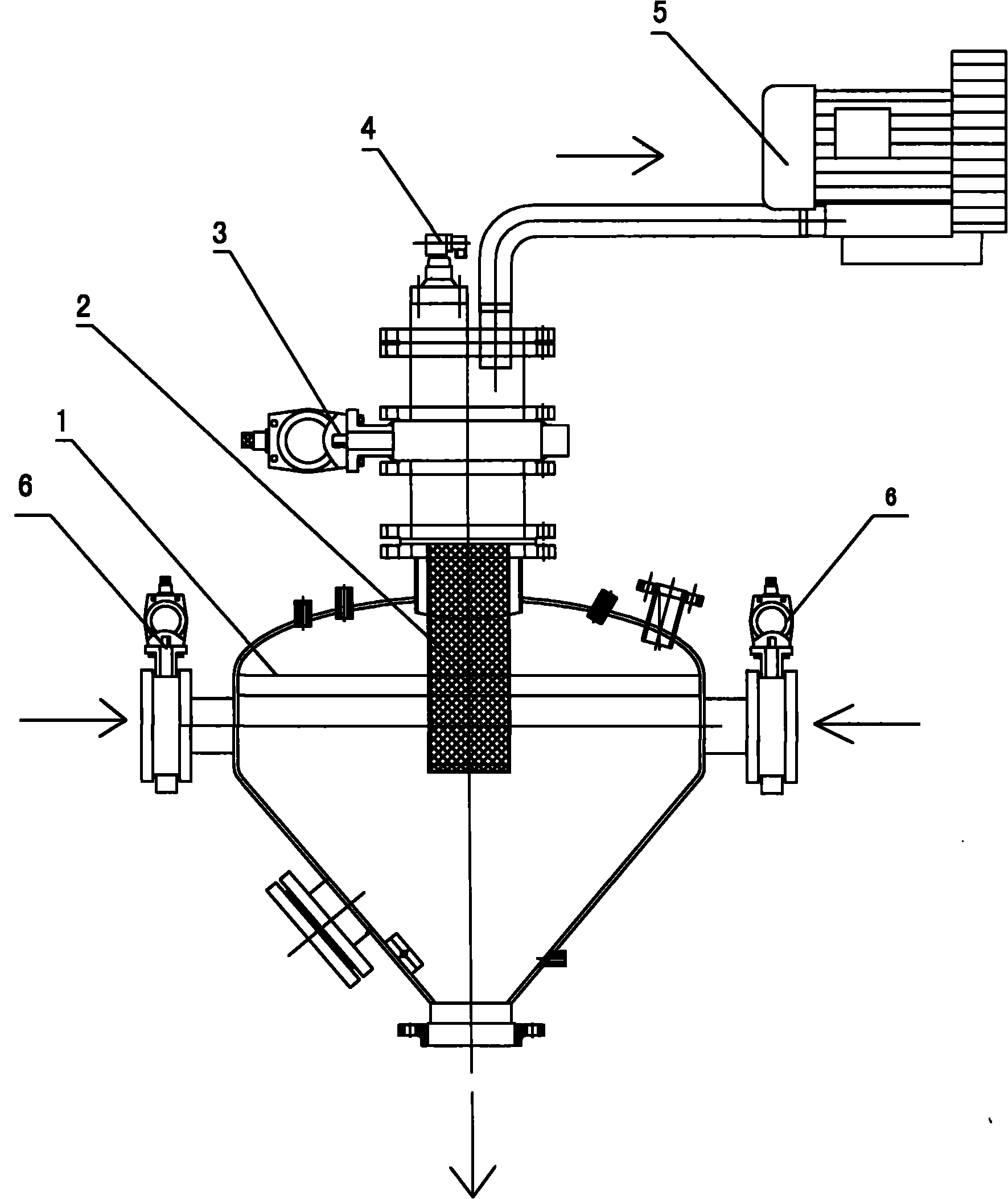
[0013] See figure 1 , the positive and negative pressure combined delivery tank of this embodiment includes: a sending tank 1, a filter element 2 located in the exhaust port on the top of the sending tank 1, a pneumatic butterfly valve 3 arranged on the exhaust port at the top of the sending tank 1, and a pneumatic butterfly valve connected to the pneumatic butterfly valve 3. The vortex suction pump 5 above, the submerged pulse solenoid valve 4 installed above the pneumatic butterfly valve 3 and connected to a high-pressure air source for blowing the adhered material on the filter element 2, and the feed material installed in the middle and upper part of the sending tank 1 The feed valve 6 on the mouth, and the suction sealing valve that is located on the discharge port at the bottom of the sending tank 1.

[0014] In order to facilitate the pressure feeding and emptying of materials, the sending tank 1 is conical.

[0015] The feed valve 6 includes a pair of symmetrical dist...


PUM


Abstract

The invention relates to a positive and negative pressure combined conveying tank with simple structure, saving time and labor, occupying less space, and suitable for quantitatively and quickly conveying materials. The pneumatic butterfly valve on the exhaust port on the top of the sending tank, the vortex suction pump connected above the pneumatic butterfly valve, the submerged pulse solenoid valve used to blow the adhered material on the filter element, the inlet on the upper part of the sending tank The material valve, and the suction sealing valve located on the material outlet at the bottom of the sending tank. The delivery tank generates negative pressure through the vortex air pump connected to the tank body, so that the tank body is in a certain negative pressure state, and the materials in the nearby silo or production equipment are sucked in through the movable or fixed installation flexible hose The tank body, when the material is filled to the set level, automatically stops feeding and closes the feed valve and exhaust valve; then automatically pressurizes the tank and carries out the pressure feeding of the material until the material is emptied.

Description

technical field [0001] The invention relates to the technical field of pneumatic conveying devices, in particular to a positive and negative pressure combined conveying tank. Background technique [0002] Traditional material transportation often adopts manual handling or conveyor belt transportation, which has low efficiency, and dust particles generated during transportation are likely to cause environmental pollution. [0003] Existing material sending tanks often adopt positive pressure conveying and feeding, and have certain requirements on the space height, because they must be fed by the gravity of the material, that is, the material needs to be transported to the feeding port on the top of the sending tank by manual handling ,Time-consuming. Contents of the invention [0004] The technical problem to be solved by the present invention is to provide a positive and negative pressure combined conveying tank which is simple in structure, saves time and effort, takes u...

Claims


Application Information

Patent Timeline
IPC IPC(8): B65G53/28B65G53/58
Inventor 季胜
Owner 季胜
Why Eureka
Try Eureka