
Key structure and keyboard apparatus

a keyboard and key technology, applied in the field of key structure and keyboard apparatus, can solve the problems of reduced weight, difficult to secure the mounting space of functional parts, and high total height of the keyboard apparatus, and achieve the effect of increasing mounting freedom and excellent machinability

Inactive Publication Date: 2007-02-01
YAMAHA CORP
View PDF42 Cites 3 Cited by
  • Summary
  • Abstract
  • Description
  • Claims
  • Application Information

AI Technical Summary

Benefits of technology

The present invention provides a key structure that can give a woody appearance to the key while still maintaining excellent machinability. The key structure includes an upper plate member, a wood part, and a lubricant-avoiding mechanism part. The wood part is secured to the upper plate member and has a recess formed therein. The recess receives at least one functional part for sliding movement relative to the key structure via a lubricant during key-depressing operation. The lubricant-avoiding mechanism part prevents lubricant from entering the wood part, to maintain required lubricating performance over a long term. The key structure can be used in a keyboard apparatus and reduces the size and weight of the keyboard apparatus.

Problems solved by technology

However, the conventional key structures have the following problems:
Therefore, it is not easy to secure the mounting space for the functional parts.
This makes it necessary to set wide spacing between the key and the frame, so that the total height of the keyboard apparatus becomes high, which is contrary not only to the demand for reduction of the size, but also to the demand for reduction of the weight since the amount of wasteful wood part increases.
However, if the recesses are small, the dimensions and types of functional parts which can be mounted are limited, which lowers the freedom of mounting.
If the thickness is reduced to about 1 mm, special working means, such as attachment of a reinforcing plate, has to be provided during machining of the woody part for adjustment of the key width, or it becomes difficult to machine wood under proper cutting conditions suited to the machining of the wood.
However, if the lubricant is directly applied to the recess formed in the wood part, there arises not only the problem that the lubricant enters the wood part to discolor the wood part, but also the problem that the lubricant eventually stops functioning properly due to dispersion and deterioration thereof.
However, the wood part expands and contracts or deforms due to changes in environmental conditions (humidity, temperature, aging, etc.), and therefore, if the key base body and the front butt end member are formed integrally with each other, or they are formed in separate bodies but substantially in contact with each other when the key structure is manufactured, the two members may interfere with each other due to expansion and contraction or deformation of the wood part, which degrades the fixation of the wood part to the two members, and in the worst case, separation of them occurs.
If the fixation of the wood part to the upper plate member, the key base body, or the front butt end member is degraded, the front end of the key can become faulty.
Thus, required durability of the key cannot be ensured.
However, if the limiting member is disposed below the front end of the key and the front butt end member is disposed in contact with the limiting member, the fixation of the wood part to the front butt end member is degraded due to a shearing force applied between the front butt end member and the wood part as the key depressing operation is repeatedly carried out.
Moreover, in the case where the keyboard apparatus has an upper plate member, if the wood part is secured to the upper plate member, and at the same time the front butt end member is provided in fixed relation to the upper plate member, the fixation of the wood part to the upper plate part is degraded due to the repeated key depressing operations.
When the fixation of the wood part to the upper plate member or the front butt end member is degraded, the front end of the key can become faulty.
Thus, required durability of the key cannot be ensured.
On the other hand, if the limiting member is disposed at a location closer to the rear end of the key so as to prevent the key from being brought into contact with the front butt end member, the limiting function is weakened due to a change in the lever ratio, which makes it difficult to perform a proper limiting operation.
However, although the key structure having resin or the like coated on the surface of the base material gives a high-grade texture due to the wood being used as the base material, this key structure is more difficult to machine compared with the resin-based key structure, and therefore it is difficult to manufacture key structures uniform in quality at low costs.
However, if these engaging parts are made of wood, high machining tolerances cannot be required of driving sections thereof, due to the limited accuracy of woodworking.
On the other hand, if the key structure is made of resin or the like as a one-piece member including the pivot and the engaging parts, a woody appearance cannot be obtained at all, and further, the touching feeling tends to be adversely affected since the rigidity of the resin key is lower compared with the wooden key.
(6) Further, in this type of key structure, “the associated element-engaging parts” and “the key functional parts” are also often formed at the wood part by machining the same, and therefore the freedom of design concerning the functions and shapes thereof is low, and the machining accuracy is low with lots of limitations on machining.
This makes it difficult to exhibit the key functions with high accuracy.

Method used


Image

  • Key structure and keyboard apparatus
  • Key structure and keyboard apparatus
  • Key structure and keyboard apparatus

Examples


first embodiment

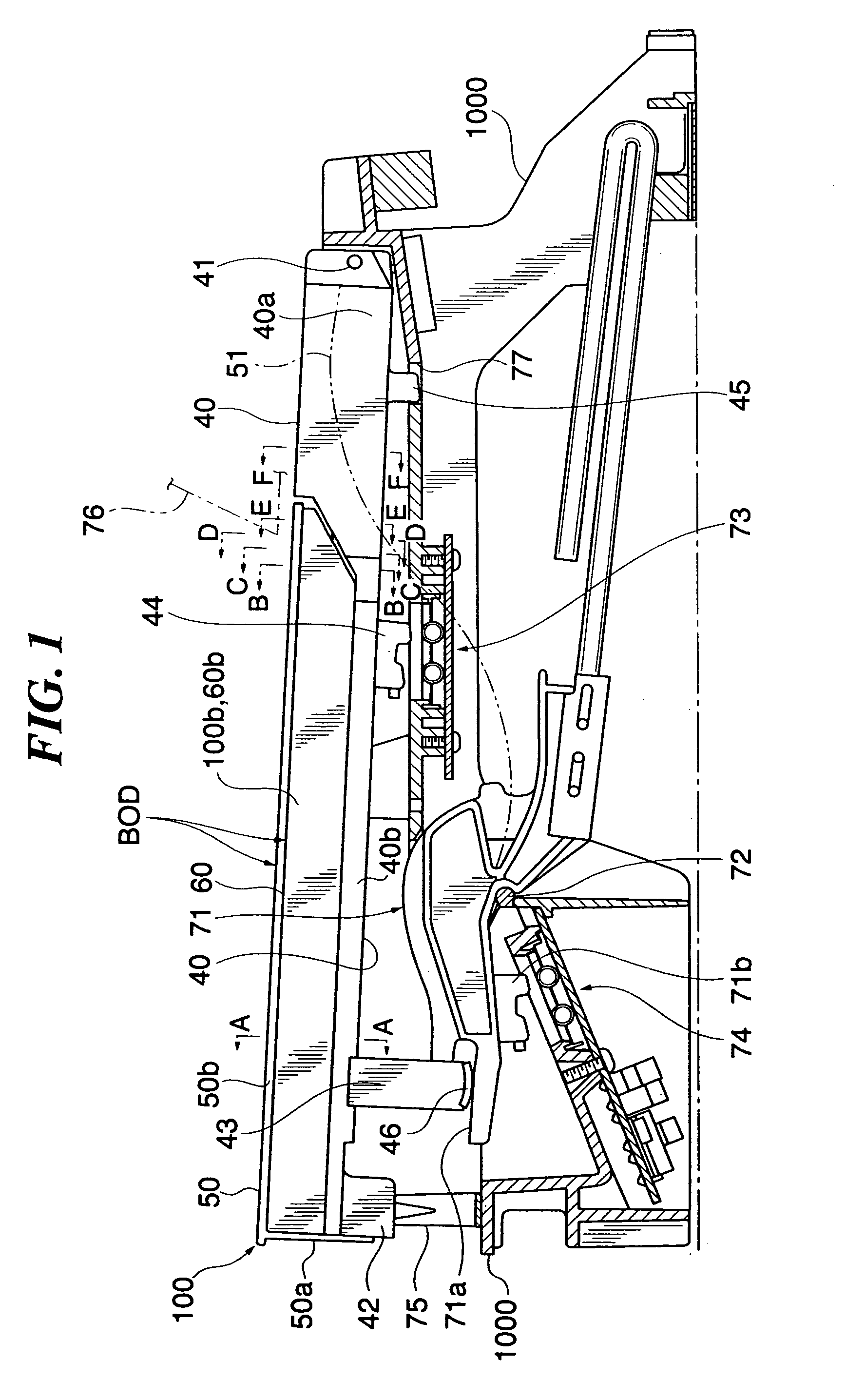
[0123]FIGS. 3A to 3D are cross-sectional views of other examples of the key structure which show a cross-section corresponding to that of FIG. 2A of the above-described embodiment.

[0124] For example, FIG. 3A shows an example in which parts corresponding to the upper plate 50 and the key base 40 are formed integrally with each other and made of resin. More specifically, an upper plate 10a and a lower plate 10c are connected by a connecting part 10b, to form a shape of laterally buckled “H”. In this example, the wood part is comprised of divided parts 20L and 20R which are arranged on the opposite lateral sides of the connecting part 10b, to thereby form a key structure.

[0125] In the case of an example in FIG. 3B, a ridge-like protrusion 31a is formed on an upper plate 31 made of resin in a fashion extending downward therefrom, and a connecting part 32a and a lower plate 32b are formed integrally with each other and made of resin, with a groove-like recess 32aa formed in the top of ...

second embodiment

[0153] The key structure 200 is configured as a B key, for example. FIG. 6 is a right side view of the key structure 200. The key structure 200 is applied to a white key, but the construction of the key structure 200 may be applied not only to a white key but also to a black key. In the following description, a side of the present keyboard apparatus and the key structure 200 toward the player will be referred to as “the front side”.

[0154] The key structure 200 is constructed such that a wood part 67 made of wood is secured to the top of a key base 68 as a holding member, and further an upper plate 123 is secured to the wood part 67. The upper plate 123 is comprised of a front butt end member 81 as a front part, and an upper plate part 66 providing a key operating surface, which are made of a synthetic resin and formed integrally with each other. The front butt end member 81 and the upper plate part 66 may be formed in separate pieces. The wood part 67, which has approximately the s...

third embodiment

[0195] Although in the third embodiment, there is illustrated an example in which the holding member that fixedly holds the wood part is formed by the upper plate 125 and the key base 55 as separate bodies, this is not limitative, but the present invention is applicable to a configuration in which the wood part is held by the upper plate alone, or the wood part is held by a holding member comprised of an upper plate and a key base formed integrally with each other.

[0196]FIG. 11 is a partial cross-sectional view of a keyboard apparatus incorporating a key structure according to a fourth embodiment of the present invention. The fourth embodiment is distinguished from the third embodiment in the shape of the recess in the key structure, and hence in the shapes of the wood part and the key base. The two embodiments are identical in construction in the other respects.

[0197] As shown in FIG. 11, the key structure 500 according to the fourth embodiment is comprised of a key base 63 as the...


PUM


Abstract

A key structure which is capable of giving a woody appearance to the key, and increasing the freedom of mounting at least one functional part formed as a separate part from the key structure, while maintaining excellent machinability. An upper plate has an increased width part corresponding to an end of a white key toward a player. In the key structure, a wood part is secured to the lower surface of at least the increased width part of the upper plate, and has an increased width part having substantially the same width as the increased width part of the upper plate. The key structure is mountable in a keyboard apparatus, for functioning as a white key pivotally moved by key-depressing operation. A recess is formed in a part of the wood part including the increased width part, which opens downward and has a width (W0) not less than 50% and not more than 80% of the width (B0) of the increased width part of the wood part.

Description

CROSS REFERENCE TO RELATED APPLICATION [0001] This application is a division of U.S. application Ser. No. 10 / 940,903 filed on Sep. 13, 2004, the entire contents of which are incorporated herein by reference. BACKGROUND OF THE INVENTION [0002] 1. Field of the Invention [0003] The present invention relates to a key structure which is applied to a key having a wood part, and a keyboard apparatus including the key structure. [0004] 2. Description of the Related Art [0005] Conventionally, key structures are known which are mounted in a keyboard apparatus and function as a key pivotally moved by key depression and for which wood or the like is used, as disclosed in Japanese Utility Model Registration Publication No. 2514485 and Japanese Laid-Open Patent Publication (Kokai) No. 2903959. In such a woody key structure, a wood material is used at least for a so-called “visible part” which is visible from the outside during both performance and non-performance, and the key structure presents a...

Claims


Application Information

Patent Timeline
Patent Type & Authority Applications(United States)
IPC IPC(8): G10C3/12G10H1/34G10B3/12
CPCG10H1/346G10C3/12
Inventor OSUGA, ICHIRONISHIDA, KENICHISHIMOMUKU, YOICHIROU
Owner YAMAHA CORP
Learn More