Composite Ribbon Laying Apparatus and Method Using Laser

A composite material and laying device technology, applied in the field of laser technology application, can solve the problems of affecting processing flexibility, reducing production efficiency, complex manufacturing process, etc., and achieve the effect of improving the laying process efficiency, simplifying the manufacturing process, and simplifying the process

Inactive Publication Date: 2011-12-07
SHANXI FEIHONG LASER TECH +2
View PDF5 Cites 16 Cited by
  • Summary
  • Abstract
  • Description
  • Claims
  • Application Information

AI Technical Summary

Problems solved by technology

However, electron beam curing technology uses electron beams as a heat source and requires a high-vacuum environment to prevent electron scattering. A vacuum chamber with a specified space must be installed on the processing table, which greatly affects the flexibility of processing. In addition, The required vacuum time also seriously reduces the production efficiency
[0005] In addition, in order to ensure better adhesion between the prepreg yarn bundle (or narrow tape) and the original layer on the mold, and to prevent air bubbles and ensure product quality , Special process equipment is required to make prepreg yarn bundles (or narrow tapes), so the manufacturing process is complicated and the manufacturing cost is increased

Method used


Image

  • Composite Ribbon Laying Apparatus and Method Using Laser
  • Composite Ribbon Laying Apparatus and Method Using Laser
  • Composite Ribbon Laying Apparatus and Method Using Laser

Examples


Embodiment Construction

[0027] Hereinafter, preferred embodiments of the present invention will be described in detail with reference to the drawings.

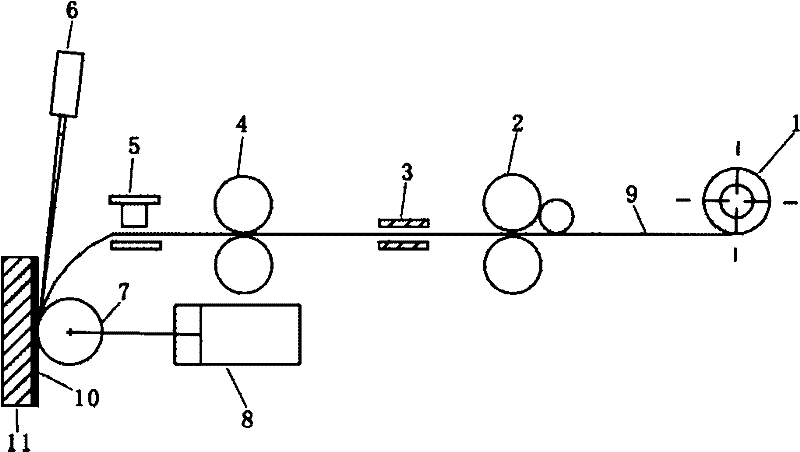
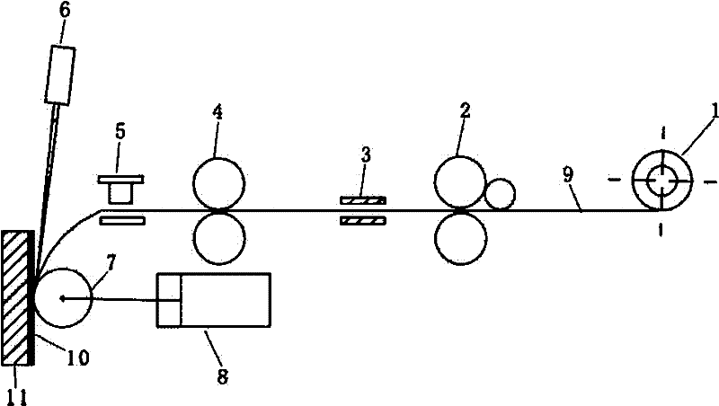
[0028] figure 1 It is a schematic diagram showing the overall structure of the composite material ribbon laying device using laser according to the present invention. As shown in this figure, the composite material ribbon laying device utilizing laser includes: as the unwinding reel 1 of the wire feeding part, the composite material ribbon is wound, and the composite material ribbon can be sent out while rotating. Here, the composite material ribbon is for example It can be a wet fiber bundle with a certain resin content; the gluing roller 2 as the gluing part, gluing the surface of the composite material ribbon sent out from the above-mentioned unwinding reel 1; the traction and clamping mechanism 3 and the guide roller as the guiding part 4. Guide and clamp the composite material ribbon after gluing, so as to stretch and convey the composite mater...


PUM


Abstract

The invention relates to a composite material ribbon laying device using laser, which has a tape unwinding roll, a glue roller, a guide unit and a pressure roller, wherein a laser device is also included, which is arranged to be able to face the processed member and the composite material ribbon The bonding part of the laser beam is used to scan point-by-point the bonding surface of the composite material ribbon laid on the processed member by using the laser beam, so that the thin layer on the surface of the scanned area undergoes a photopolymerization reaction and reaches a cured state. According to the present invention, the continuous laser curing process is used to scan the surface of the ribbon of the composite material point by point during the laying process of the composite material to make it reach a solidified state, and then press it with a pressure roller to form the profile of the product.

Description

technical field [0001] The invention relates to a composite material ribbon laying device using laser and a method thereof, which are used in the field of aviation manufacturing to use a laser device to assist in laying composite material ribbons for aircraft, and belong to the application field of laser technology. Background technique [0002] Composite materials have the advantages of light weight, high strength, high modulus, integration of structure and function, integration of design and manufacture, and easy manufacture of large components, etc., and are widely used in the aerospace industry. The amount of composite materials has become one of the important indicators to evaluate the advanced nature of aerospace vehicles, so the amount of composite materials used in aircraft is increasing day by day. With the continuous increase of aircraft structure size and the increasing use of aircraft composite materials, special equipment and technologies for manufacturing compo...

Claims


Application Information

Patent Timeline
Patent Type & Authority Applications(China)
IPC IPC(8): B29C65/52B29C35/08
Inventor 王智勇史元魁许并社辛立军陈玉士王有顺王文先
Owner SHANXI FEIHONG LASER TECH
Why Eureka
Try Eureka