
cutting stapler

A suturing device and matching technology, applied in the field of medical devices, can solve problems such as difficulty in firing, inability to push, increase friction between the firing piece and the right side wall of the sliding groove, etc., and achieve the effect of easy firing and convenient operation

Inactive Publication Date: 2011-12-07
朱春林
View PDF6 Cites 2 Cited by
  • Summary
  • Abstract
  • Description
  • Claims
  • Application Information

AI Technical Summary

Problems solved by technology

[0006] Since the distal end of the cutting stapler is deflected to the left, based on this design idea, the firing piece that pushes the blade assembly (including the cutting blade and the nail pushing piece) should also deflect to the left together at the turning point, resulting in pushing the firing piece. When the button fires the blade assembly, as the blade assembly is against the tissue, the front resistance immediately increases, and the firing piece will deflect to the right and cling to the right side wall of the sliding groove. On the one hand, the firing thrust is consumed, and on the other hand, the firing piece increases. The friction between the right side wall of the sliding groove makes the firing very difficult or even impossible to push

Method used


Image

  • cutting stapler
  • cutting stapler
  • cutting stapler

Examples


Embodiment Construction

[0027] Attached below Figure 3-Figure 9 , the embodiment of the present invention will be described in detail.

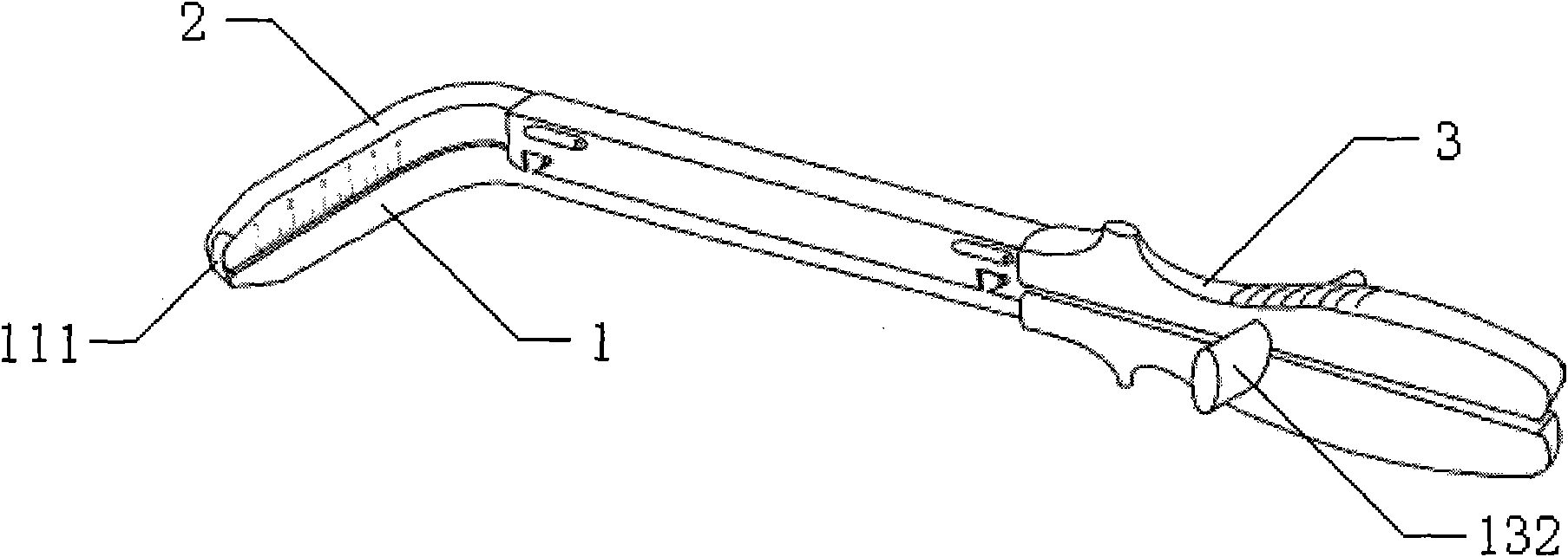
[0028] refer to Figure 3-Figure 5 , the present embodiment mainly includes a staple cartridge assembly 1, an anvil assembly 2 cooperating with the staple cartridge assembly 1 up and down, and a closing handle 3 connected with the staple anvil assembly 2, and the staple cartridge assembly 1 and the staple anvil assembly 2 respectively include a The cutting and suturing ends 11, 21, the intermediate connecting parts 12, 22, and the holding ends 13, 23, wherein:

[0029] The cutting and suturing ends 11, 21 of the staple cartridge assembly 1 and the staple anvil assembly 2 are smoothly deflected by a preset angle relative to the middle connecting portion 12, 22 and the gripping end 13, 23; and

[0030] Please refer to Figure 5 , Figure 6 and Figure 9 , the staple cartridge assembly 1 includes a blade assembly 112 arranged in the slide groove 110 and a staple ...


PUM


Abstract

The embodiment of the invention discloses an incision stitching instrument, which comprises a nail bin assembly, a nail anvil assembly and a closed handle, wherein the incision stitching end of the nail bin assembly and the incision stitching end of the nail anvil assembly deflect a preset angle smoothly relative to an intermediate junction part and the gripping end; the nail bin assembly comprises a blade assembly arranged in a sliding groove and a nail bin arranged above the sliding groove; the blade assembly is arranged at the front end of the nail bin, and is connected with a trigger button by a trigger sheet; the trigger sheet extends to the gripping end of the nail bin assembly along the incision stitching end and the intermediate junction part of the nail bin assembly; the trigger button is arranged at the gripping end of the nail bin assembly; and during triggering, the trigger button is pulled in the tail end direction of the gripping end of the nail bin assembly to drive theblade assembly to slide towards the nail bin in the sliding groove. By the incision stitching instrument, deep tissue can be incised effectively in an omnibearing mode, and the incision stitching instrument is flexible in triggering, convenient to operate and stable in a structure.

Description

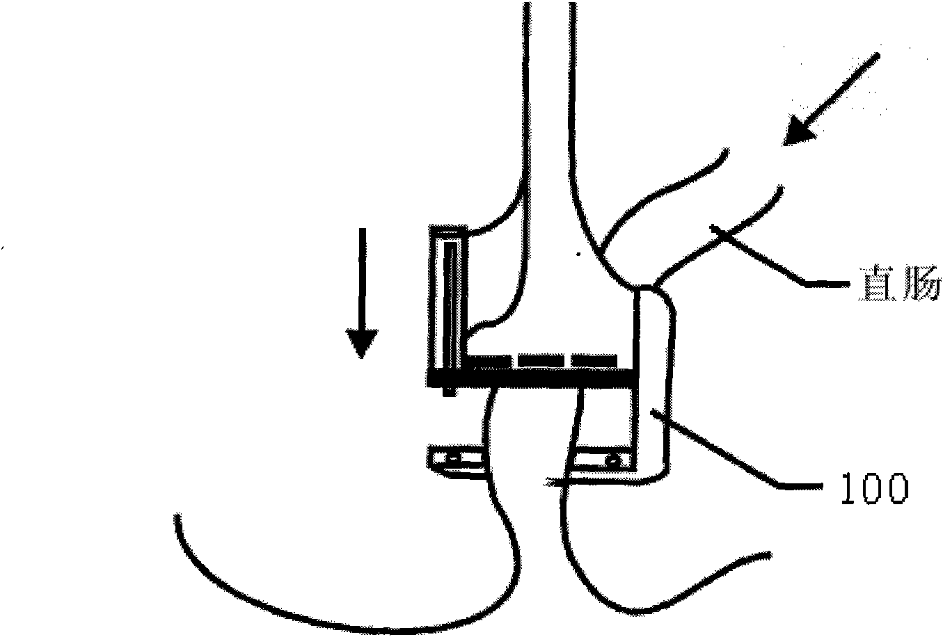
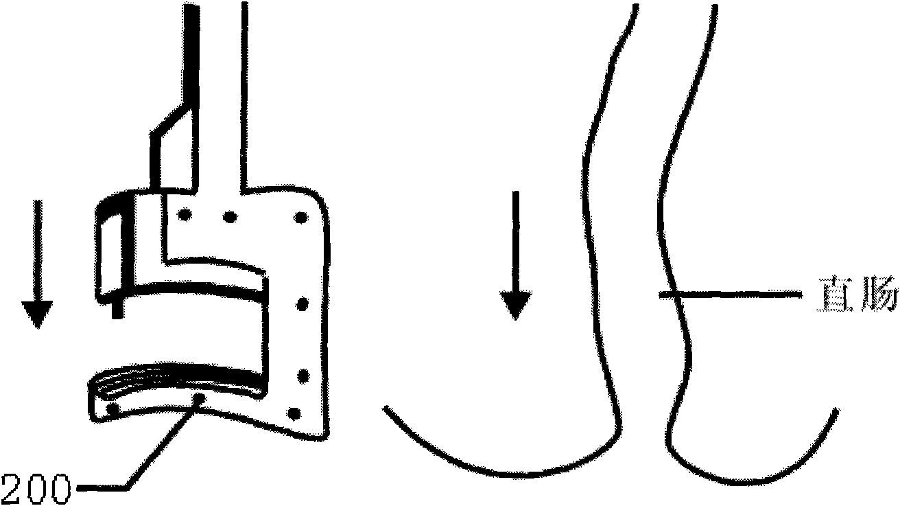
technical field [0001] The invention relates to the field of medical instruments, in particular to a cutting and stapler used in surgical operations. Background technique [0002] During surgical operations, the removal of deep tissue is undoubtedly one of the difficulties that all surgeons will encounter. The difficulties are mainly reflected in two aspects: on the one hand, the surgical field of view is narrow and the size of slightly larger surgical instruments (including cutting stapler) cannot be lowered to the surgical site; refer to figure 1 On the other hand, the running direction of the tissue and organ is parallel to the direction of the instrument jaw 100. The surgeon needs to find a way to make the blade of the instrument form an angle with the running direction of the tissue and organ, so as to be able to cut the tissue and organ. Of course, such an operation is very not easy. [0003] For example, this is the case in low anterior rectal resection surgery. As ...

Claims


Application Information

Patent Timeline
IPC IPC(8): A61B17/072
Inventor 朱春林
Owner 朱春林
Learn More