Switching apparatus for electrical contact testing

A switchgear and electrical contact technology, which is applied in the parts of electrical measuring instruments, measuring electrical variables, electronic circuit testing, etc., can solve the problems of destroying printed wires, inability to test adapter tests, low mechanical stability, etc.

Active Publication Date: 2014-11-05
ASMAG HLDG
View PDF7 Cites 0 Cited by
  • Summary
  • Abstract
  • Description
  • Claims
  • Application Information

AI Technical Summary

Problems solved by technology

However, this configuration also has the disadvantage that the necessary pressing force of the contact pins can damage or destroy the conductor tracks to be tested
[0006] A further important disadvantage of the described method is that printed circuits or printed conductor tracks cannot be tested reliably with known test adapters or with contact pins, since the printed Guidance wire will not pass the test without damage
The disadvantage here is that there must be a laser source which has to be deflected by a complex deflection system, in particular several precisely controlled mirrors
Disadvantage also lies in: the photoconductive layer is arranged directly on the printed conductor
Due to inaccuracies in the irradiation of the laser beam or due to control influences, it may occur that a larger area of ​​the photoconductive layer is illuminated and thus becomes conductive, possibly resulting in electrical contact of adjacent printed conductors

Method used


Image

  • Switching apparatus for electrical contact testing
  • Switching apparatus for electrical contact testing
  • Switching apparatus for electrical contact testing

Examples


Embodiment Construction

[0057] First of all, it should be pointed out that in different described embodiments, the same components have the same reference numerals or the same component designations, wherein the disclosure contained in the entire description can be interpreted as having the same reference numerals or the same component designations. same parts. Furthermore, orientation indications mentioned in the description, such as top, bottom, side, etc., relate to the directly corresponding description and to the illustrated figure and can be sensibly converted to a new orientation in the event of an orientation change. Furthermore, individual features or combinations of features from the various exemplary embodiments shown and described can themselves form independent, inventive or inventive solutions.

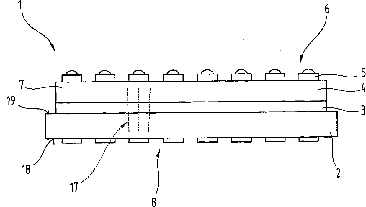
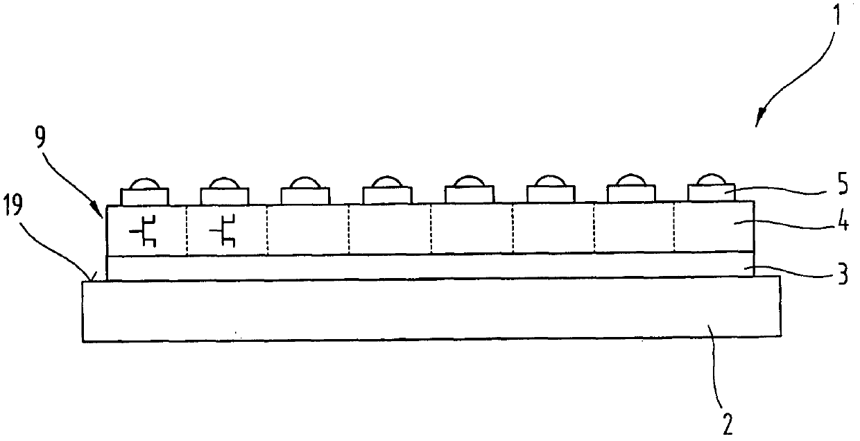
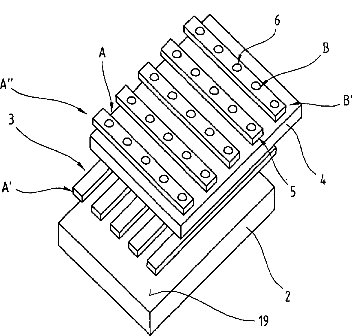
[0058] figure 1 A switching device 1 according to the invention is shown, comprising a carrier layer 2 , a first electrode system 3 , a functional layer 4 , a second electrode system 5 as well...


PUM


Abstract

The invention relates to a switching apparatus (1) for conducting electrical contact tests on bare and assembled printed circuit boards (12), comprising at least a flat support layer (2), a first electrode arrangement (3) and a functional layer (4), which support layer (2) is elastically restorably deformable, and the functional layer (4) is disposed on top of the first electrode arrangement (3). The functional layer (4) is made from at least one of the group comprising a layer of a photosensitive material (7), a quantum detector and a photoresistor, and at least one source for electromagnetic radiation (8) is additionally disposed above the functional layer (7), and the emitted electromagnetic radiation predominantly acts in the direction of the functional layer (4). The functional layer (4) may also be provided in the form of a transistor arrangement (9) made up of a plurality of transistors. The invention further relates to a method of producing a switching apparatus (1).

Description

technical field [0001] The invention relates to a switchgear for electrical contact testing of assembled and unassembled printed circuit boards, comprising at least one planar carrier layer, a first electrode system and a functional layer, wherein the carrier layer can be elastically The way of reset is deformed and the functional layer is arranged on the first electrode system. The invention also relates to a method for producing such a switchgear. Background technique [0002] For the construction of electronic circuits, preferably printed circuit boards are used, on which electronic parts and components are mounted in a further processing step. The printed circuit board is preferably formed from a carrier layer and conductor tracks arranged thereon. Since the reliability of the electrical connections of printed circuit boards is of great importance for the function of the electronic circuits constructed therefrom, every printed circuit board is checked for its electrica...

Claims


Application Information

Patent Timeline
Patent Type & Authority Patents(China)
IPC IPC(8): G01R31/28
CPCG01R1/071G01R31/2808
Inventor K·施勒特尔
Owner ASMAG HLDG
Why Eureka
Try Eureka