Method and device for cutting brittle material substrate, and window glass for vehicles
A technology for brittle material substrates and glass plates, applied in glass cutting devices, fine working devices, glass production, etc., can solve problems such as unexplained cutting of substrates, and achieve excellent cross-sectional quality
- Summary
- Abstract
- Description
- Claims
- Application Information
AI Technical Summary
Problems solved by technology
Method used
Image
Examples
Embodiment 1~4
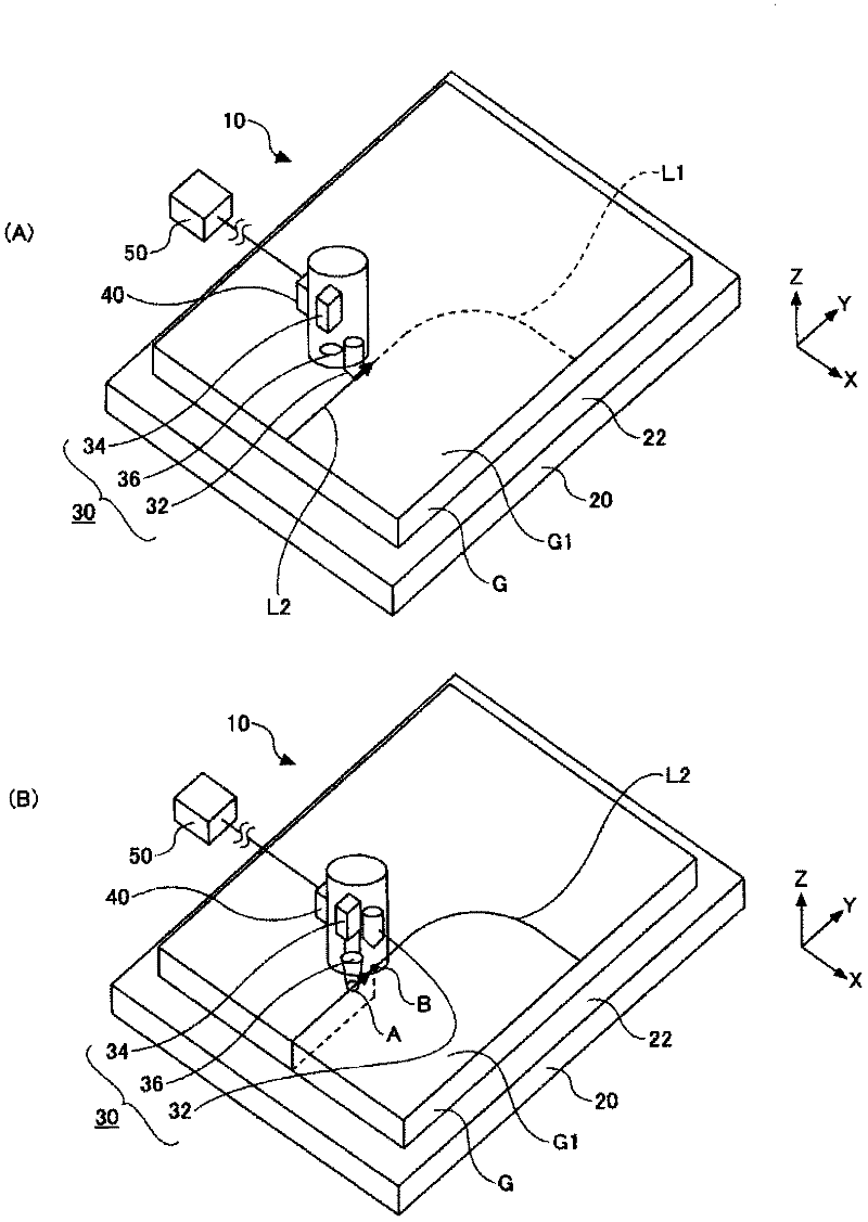
[0079] A 3.5 mm-thick green-based soda-lime glass plate (manufactured by Asahi Glass Co., Ltd.: glass substrate for automobiles) produced by the float method was prepared. Install the glass plate G on figure 1 stage 20 is shown. Next, the scriber 32 was pressed against the surface G1 of the glass plate with a force of 55N, and the scribed line L2 was drawn at a speed of 200 mm / sec. Such as Figure 4 As shown, the scribe line L2 successively has a first linear portion L2-1, a quarter arc portion L2-2, and a second linear portion L2-3. Table 1 shows the shape of the scribe line L2 in each of Examples 1-4. In addition, the said 1 / 4 arc-shaped part means the part which becomes 1 / 4 of a circle when drawing a circle using this arc (the same applies hereinafter).
[0080] [Table 1]
[0081]
[0082]
[0083] Next, the surface G1 of the glass plate G is irradiated with image 3 In the illustrated laser, the irradiation position A of the laser on the substrate surface G1 is...
Embodiment 5~7、 comparative example 3
[0094] In Examples 5-7 and Comparative Example 3, the scribe line L2 was formed similarly to Examples 1-4 except having formed the linear scribe line L2 in the center of the glass plate surface. Next, use figure 2 The indicated lasers cut the glass plate under the conditions described in Table 3. Table 3 shows the amount of glass shavings at the time of cutting and the evaluation results of the quality of the cut surface.
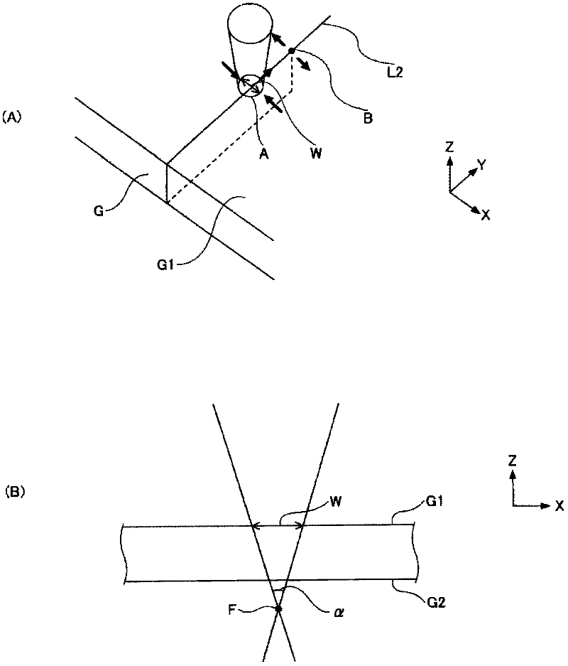
[0095] According to Table 3, in Examples 5 to 7, since the dimension W on the substrate surface G1 was set within the range of 2 to 10 mm, the quality of the fractured surface was good. On the other hand, in Comparative Example 3, the dimension W on the substrate surface G1 was too small at 1 mm. Therefore, the scribe line L2 is overheated, starting from the fine cracks when the scribe line L2 was formed, the cracks also propagate in the in-plane direction (X direction, Y direction), and the quality of the fractured surface deteriorates.
[0096] [table...
Embodiment 8~14、 comparative example 4~8
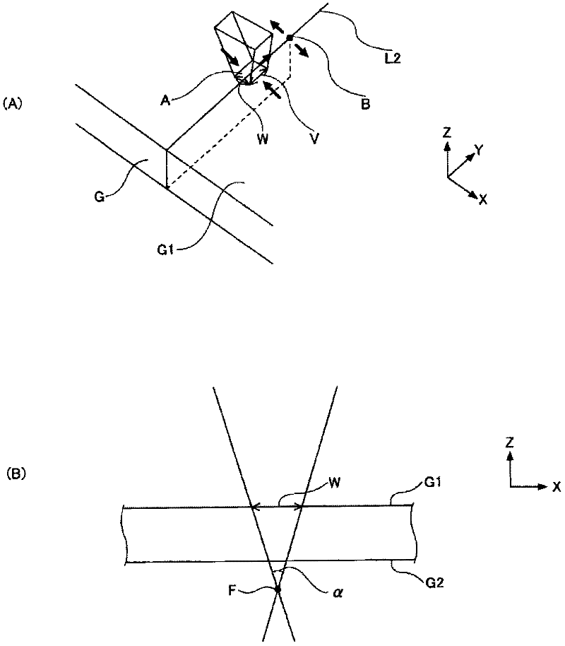
[0099] In Examples 8-14 and Comparative Examples 4-8, the scribe line L2 was formed similarly to Examples 5-7. Next, use figure 2 or image 3 The indicated lasers cut the glass plate under the conditions described in Table 4. Table 4 shows the amount of glass shavings at the time of cutting and the evaluation results of the quality of the cut surface.
[0100] According to Table 4, in Examples 8 to 14, the focusing angle α was set within the range of 10 to 34°. As a result, the quality of the fractured surface was good. On the other hand, in Comparative Examples 4 to 6, the focusing angle α was too small at 0° and 8°, and the quality of the fractured surface was lowered. This is estimated to be because the thermal stress difference between the substrate surface G1 and the substrate back surface G2 is too small. In addition, in Comparative Examples 7 to 8, the focusing angle α was too large at 60°, and the quality of the fractured surface deteriorated. It is estimated th...
PUM
| Property | Measurement | Unit |
|---|---|---|
| thickness | aaaaa | aaaaa |
| thickness | aaaaa | aaaaa |
Abstract
Description
Claims
Application Information
 - R&D Engineer
- R&D Manager
- IP Professional
- Industry Leading Data Capabilities
- Powerful AI technology
- Patent DNA Extraction
Browse by: Latest US Patents, China's latest patents, Technical Efficacy Thesaurus, Application Domain, Technology Topic, Popular Technical Reports.
© 2024 PatSnap. All rights reserved.Legal|Privacy policy|Modern Slavery Act Transparency Statement|Sitemap|About US| Contact US: help@patsnap.com


