Eureka AIR delivers breakthrough ideas for toughest innovation challenges, trusted by R&D personnel around the world.

Swirl side suction oil pump

A technology for oil suction pumps and oil well pumps, which is applied to pumps, pumps with flexible working elements, liquid displacement machinery, etc. It can solve the problems of piston fixed valve fixed valve ball seat piercing and increased mining difficulty, etc., to achieve pump The effect of small external diameter

Inactive Publication Date: 2011-11-30
CHINA PETROLEUM & CHEM CORP +1
View PDF4 Cites 7 Cited by
  • Summary
  • Abstract
  • Description
  • Claims
  • Application Information

AI Technical Summary

Problems solved by technology

This type of oil pump has been dominated by simple design, easy processing and convenient use in the early stage of oilfield exploitation, and it is still playing an important role. However, in the middle and late stages of oilfield exploitation, the well conditions of oil wells are constantly changing. In particular, the emergence of sand production at the bottom of the well and sand buried oil layers have made mining more difficult, resulting in frequent occurrences of the current direct pumping pump piston being stuck, the fixed valve being blocked, and the ball seat of the fixed valve being pierced.

Method used


Image

  • Swirl side suction oil pump
  • Swirl side suction oil pump
  • Swirl side suction oil pump

Examples


Embodiment Construction

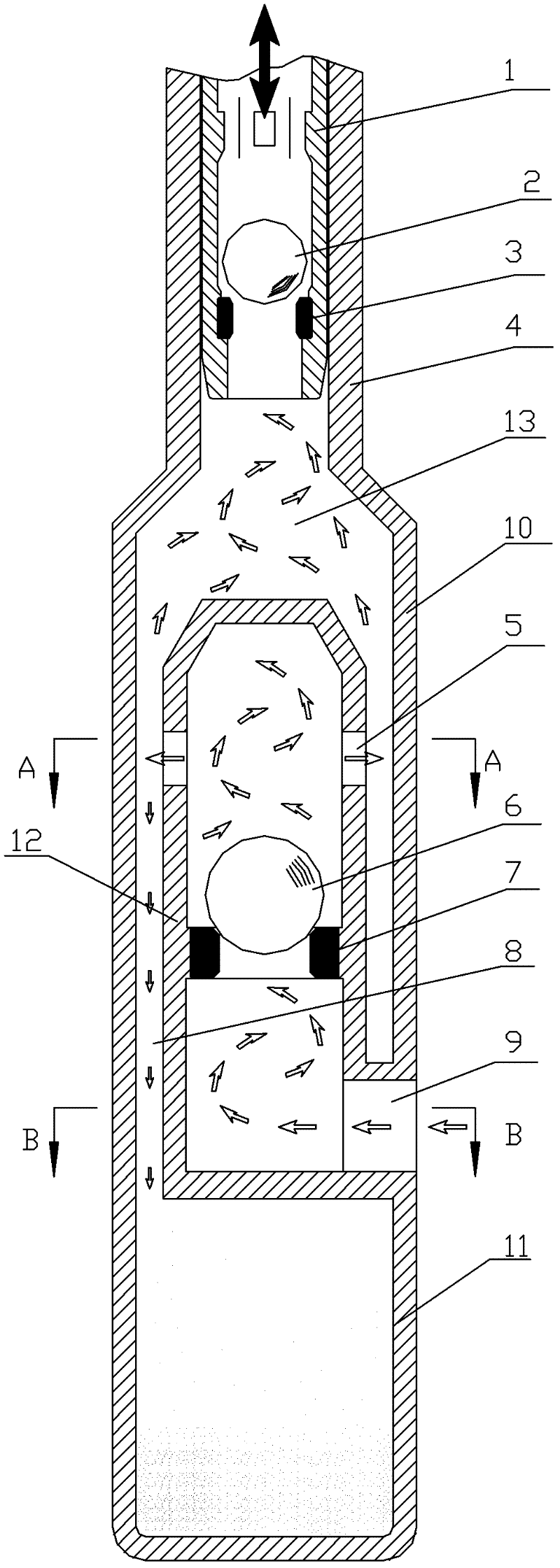
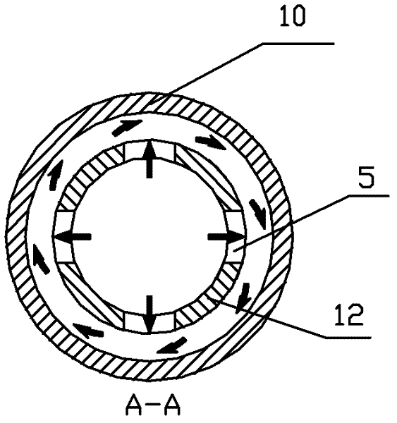
[0017] figure 1 It is a structural schematic diagram of an embodiment of the present invention, figure 2 for figure 1 A-A sectional view of, image 3 for figure 1 The B-B sectional view of B-B includes a suction oil pump, the lower end of the suction oil pump is connected with a cyclone separation cylinder, and the lower end of the cyclone separation cylinder is connected with the grit chamber 11, and the cyclone separation cylinder includes an outer cylinder 10 and an inner cylinder 12, The outer cylinder 10 is connected with the suction oil pump and the grit chamber 11 respectively. The inner cylinder 12 is installed in the inner cavity of the outer cylinder 10 and is isolated from the inner cavity of the outer cylinder as a whole, so that the circumference between the outer circumference of the inner cylinder and the inner cavity of the outer cylinder An annular flow channel 8 and an oil chamber 13 are formed to and above, and a tangential oil inlet hole 9 communicating...


PUM


Abstract

The invention provides a swirl side suction oil pump, including a suction oil pump, which is characterized in that the lower end of the suction oil pump is connected with a swirl separation cylinder, and the lower end of the swirl separation cylinder is connected with a sand settling cylinder, and the swirl separation cylinder It includes an outer cylinder and an inner cylinder. The upper and lower sides of the outer cylinder are respectively connected with the suction oil pump and the sand chamber. An annular flow channel and an oil chamber are formed in the circumferential direction and above, and a tangential oil inlet hole connected to the lower inner cavity of the inner cylinder is opened under the outer cylinder. A one-way ball valve is installed in the inner cavity of the inner cylinder. The side wall of the inner cylinder above the ball valve is provided with a lateral oil outlet hole communicating with the annular flow channel. Break through the existing direct pumping method, enter the liquid from the side of the pump body, use rotary pumping, use the principle of centrifugal force to separate the sand and oil, and prevent the sand-containing liquid from directly entering the piston and the floating valve, causing the piston to be stuck and the valve to be fixed Blockage, puncture of fixed valve ball seat, etc. occur frequently.

Description

technical field [0001] The invention relates to an oil well pump in the field of oil exploitation. Background technique [0002] The oil well pump is an indispensable equipment for the oil production of the pumping well, and what the oil well pump used at present adopts the direct suction type oil well pump. This type of oil pump has been dominated by simple design, easy processing and convenient use in the early stage of oilfield exploitation, and it is still playing an important role. However, in the middle and late stages of oilfield exploitation, the well conditions of oil wells are constantly changing. In particular, the emergence of sand production at the bottom of the well and sand buried oil layers have made mining more difficult, resulting in frequent occurrences of the current direct pumping pump piston being stuck, the fixed valve being blocked, and the ball seat of the fixed valve being pierced. . Therefore, the use of reasonable and scientific oil production t...

Claims


Application Information

Patent Timeline
Patent Type & Authority Applications(China)
IPC IPC(8): F04B47/00
Inventor 吴继农夏志刚黎瑶高原谢义华张炜杨严红曹庆保李欣
Owner CHINA PETROLEUM & CHEM CORP
Why Eureka
Eureka Blog
Learn More