
Current adaptive protecting method

A self-adaptive, current technology, applied in emergency protection circuit devices, electrical components, etc., can solve problems such as failure, deterioration of protection performance, not setting value, etc.

Active Publication Date: 2014-05-07
NORTH CHINA ELECTRIC POWER UNIV (BAODING)
View PDF2 Cites 0 Cited by
  • Summary
  • Abstract
  • Description
  • Claims
  • Application Information

AI Technical Summary

Problems solved by technology

Although this harsh setting condition can ensure the correct operation of the protection, it also has obvious defects: the setting value of the protection is not the best setting value in other operating modes (including the main operating mode of the system); in the most unfavorable short circuit Under these conditions, the protection performance is seriously deteriorated or even fails.

Method used


Image

  • Current adaptive protecting method
  • Current adaptive protecting method
  • Current adaptive protecting method

Examples


Embodiment Construction

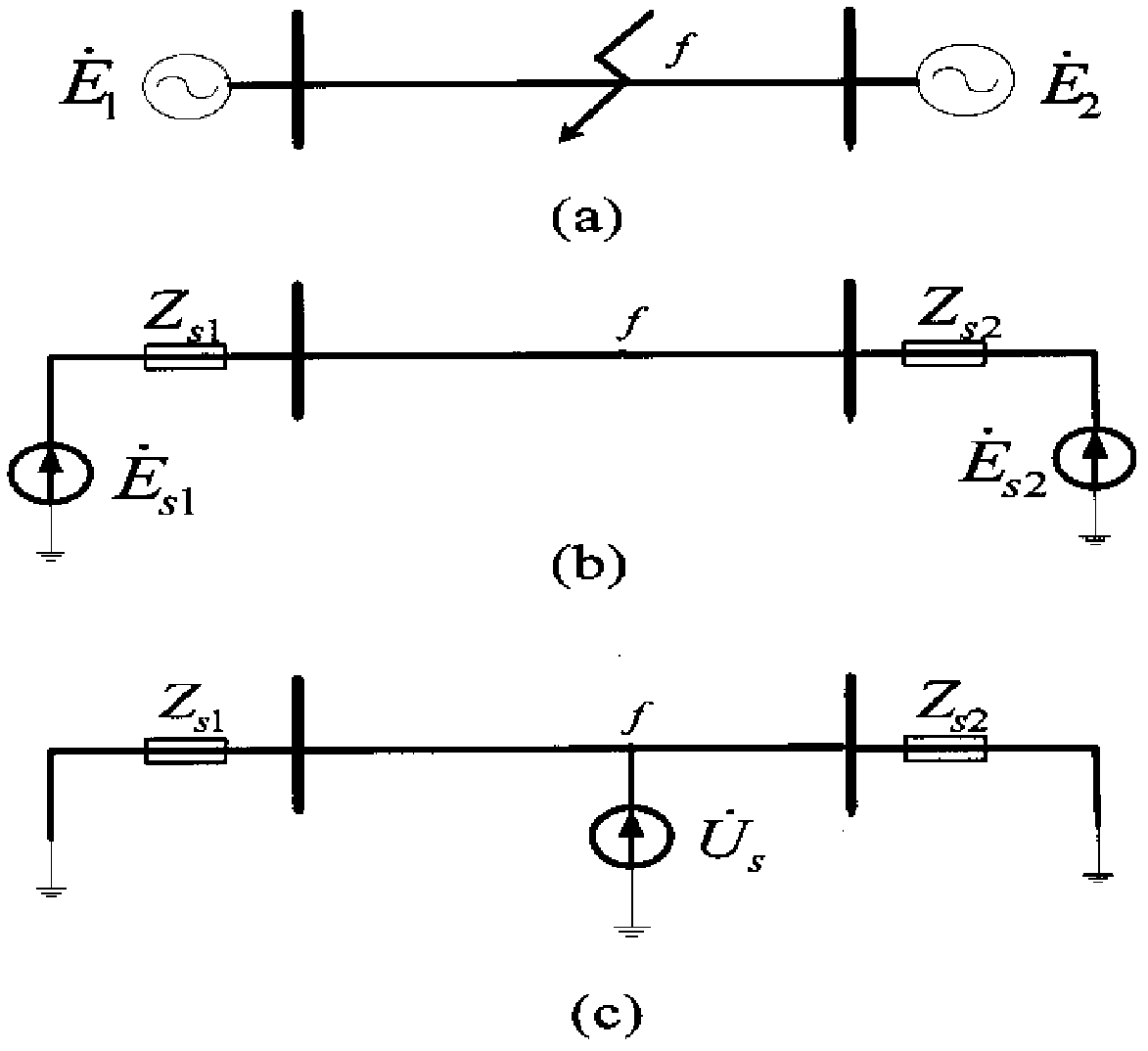
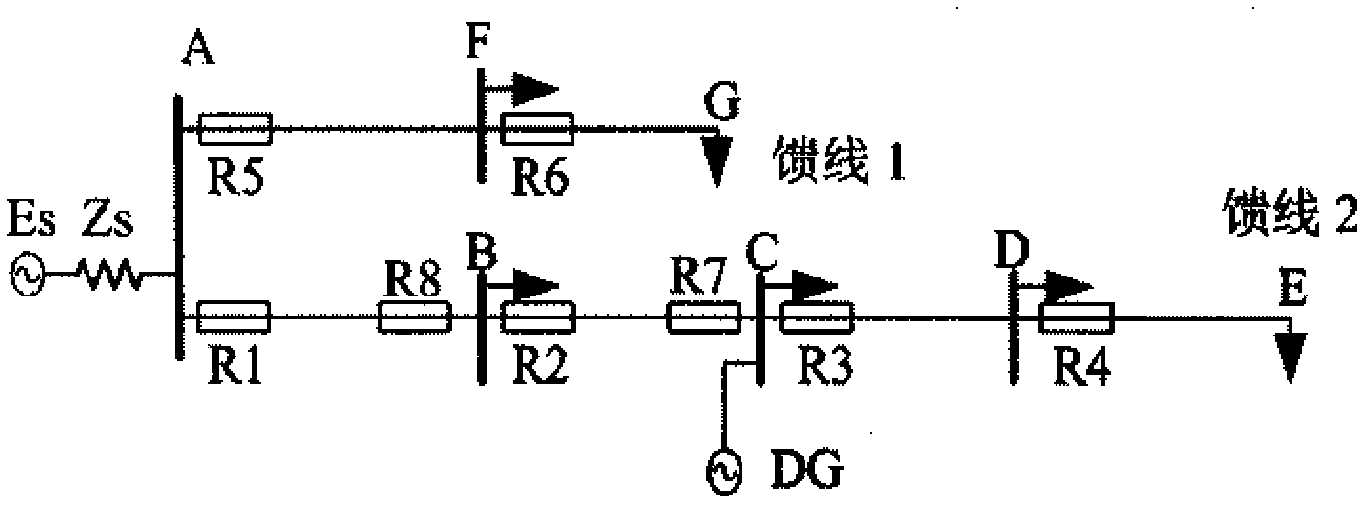
[0082] The invention provides a current adaptive protection method. The present invention mainly uses distributed IEDs to obtain network topology and system operation status information, and simplifies the fault steady-state network according to the equivalent value of these information, extracts the fault steady-state voltage of each node and the fault steady-state current of each branch, and obtains the The relationship between the node voltage and the fault steady-state injection current, using the network system parameter matrix to form the mapping relationship between the fault steady-state injection current and the fault steady-state branch current, using the fault steady-state current of the relevant branch to construct current adaptive protection. Describe below in conjunction with accompanying drawing.

[0083] Step 1 Initialization

[0084] Construct the original system data file, the collection volume includes

[0085] 1) System nodes (busbars): The collection con...


PUM


Abstract

The invention discloses a current adaptive protecting method which belongs to the technical field of an electric power system. The current adaptive protecting method comprises the following steps: utilizing a fault network equivalence simplifying method and a fault steady state component theory to obtain a relation between a node voltage and a fault steady state injection current before failure happens; utilizing a network system parameter matrix to construct the linear mapping relation between the fault steady state injection current and a fault steady state branch current; and utilizing a fault steady state current of a related branch to form novel current adaptive protection. According to the invention, the network system parameter matrix is used for eliminating the effect of a distributed power supply on the fault steady state current of each branch, thereby avoiding a protective relaying false operation caused by the accessing of the distributed power supply. A setting algorithm is simpler and more practical. A main protection scope is 72.88%-72.94% of the full length of a circuit. A protection scope of spare protection which extends to a subordinate circuit is less than the protection scope of main protection; therefore the demand of protection matching is met.

Description

technical field [0001] The invention belongs to the technical field of power systems, and in particular relates to a current self-adaptive protection method. More specifically, it involves a novel power system relay protection method using the fault steady-state component theory. Background technique [0002] The traditional relay protection uses the maximum operation mode to calculate the protection setting value, and the minimum operation mode to verify the sensitivity of the protection. Although this harsh setting condition can ensure the correct operation of the protection, it also has obvious defects: the setting value of the protection is not the best setting value in other operating modes (including the main operating mode of the system); in the most unfavorable short circuit Under these conditions, the protection performance will deteriorate seriously or even fail. In addition, with the access of distributed power sources, the operation mode of the power grid has b...

Claims


Application Information

Patent Timeline
Patent Type & Authority Patents(China)
IPC IPC(8): H02H7/26
Inventor 马静王希王增平王彤叶东华
Owner NORTH CHINA ELECTRIC POWER UNIV (BAODING)
Learn More