
Optimization design method of impeller for cavitation-erosion-resistant centrifugal fan

A centrifugal pump impeller, optimized design technology, applied in the direction of pumps, pump components, mechanical equipment, etc., can solve the problems of backward optimization design methods, low efficiency, poor cavitation performance, etc.

Inactive Publication Date: 2013-03-13
XIAN UNIV OF TECH
View PDF2 Cites 0 Cited by
  • Summary
  • Abstract
  • Description
  • Claims
  • Application Information

AI Technical Summary

Problems solved by technology

[0003] The existing centrifugal pumps in my country generally have low efficiency and poor cavitation performance. The main reason is that the optimal design method is outdated.
The flow inside the centrifugal pump is a complex full three-dimensional viscous flow, and there are complex unsteady flows including secondary flow and separation flow inside. Most of the optimal design of centrifugal pump impellers now adopts the one-element or two-element theory, although there are Some manufacturers and research institutes use the full ternary design method, but the full ternary design method is based on the inviscid assumption, and cannot accurately obtain the impeller shape that conforms to the internal flow characteristics of the centrifugal pump impeller.

Method used


Image

  • Optimization design method of impeller for cavitation-erosion-resistant centrifugal fan
  • Optimization design method of impeller for cavitation-erosion-resistant centrifugal fan
  • Optimization design method of impeller for cavitation-erosion-resistant centrifugal fan

Examples


specific Embodiment

[0084] The method of the present invention is used to optimize the design of a centrifugal pump impeller with an original impeller diameter of 720mm, blade number of 9, rotational speed of 960r / min, and flow design of 440L / s.

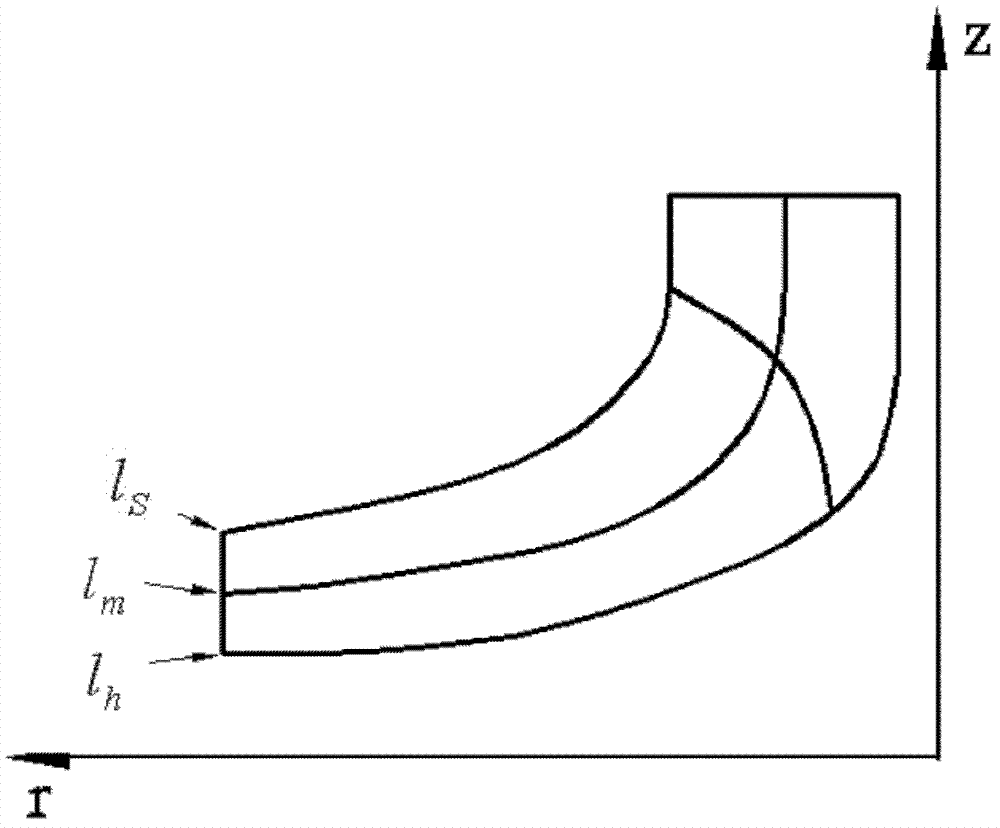
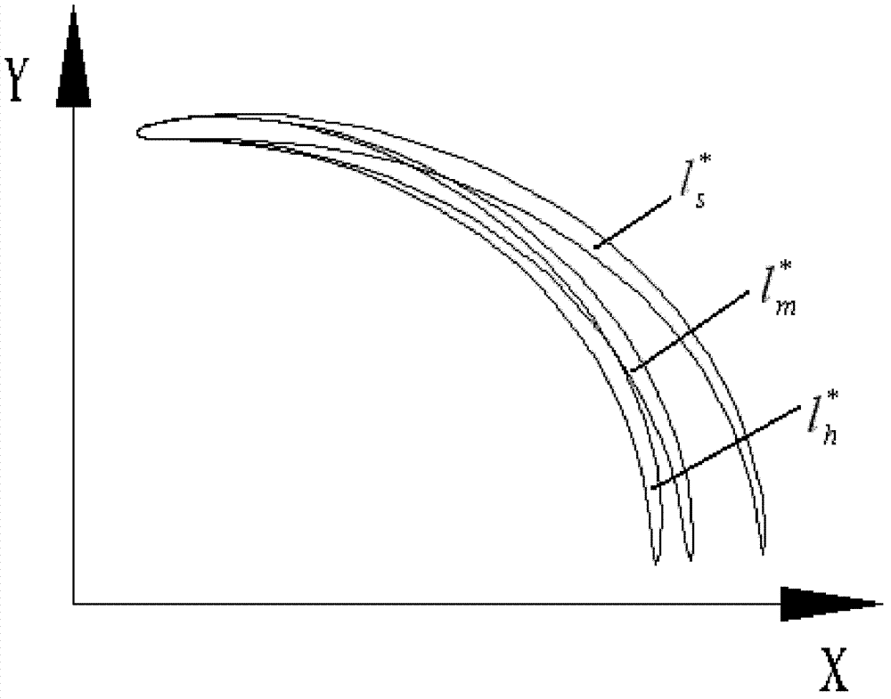
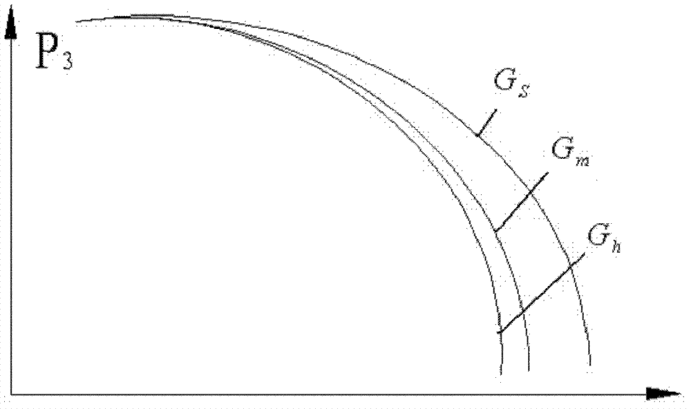
[0085] Step 1. Obtain the two-dimensional airfoil bone line G of the front cover on the circumferential XY plane of the original impeller s , the middle two-dimensional airfoil bone line G m And the two-dimensional airfoil bone line G of the rear cover h . Among them, such as figure 1 As shown, the streamline l of the front cover is obtained from the axial plane projection of the original impeller s , middle streamline l m and the streamline of the rear cover l h . Such as figure 2 Shown is the two-dimensional airfoil profile of the front cover of the original impeller Intermediate 2D airfoil profile And the two-dimensional airfoil profile line of the rear cover Such as image 3 shown, for figure 2 The two-dimensional airfoil bone line ...


PUM


Abstract

The invention discloses an optimization design method of an impellor for a cavitation-erosion-resistant centrifugal fan. The method is characterized by acquiring a front cover plate two-dimensional airfoil epiphyseal line, an intermediate two-dimensional airfoil epiphyseal line and a rear cover plate two-dimensional airfoil epiphyseal line on a circumferential XY plane of an original impellor; constructing impellor optimization parameters after parameterization, and constructing an epiphyseal line after variation; inputting the front cover plate two-dimensional airfoil epiphyseal line, the intermediate two-dimensional airfoil epiphyseal line and the rear cover plate two-dimensional airfoil epiphyseal line which are acquired through three dimension variation into a geometric modeling software, thus an impellor three-dimensional shape after variation is formed; measuring and calculating water conservation performances on the basis of single channel meshing; taking a non-dominated sorting genetic algorithm (NSGA-II) of a multi-objective genetic algorithm as an optimization tool, and carrying out multi objective optimization design on the impellor parameters of the centrifugal fan; and selecting a group of impellor parameters with optimal water conservation performance as the impellor parameter after optimization. The method provided by the invention has scientific construction ofoptimization parameters, the optimization process has high automatic degree, the impellor and blade efficiency of the centrifugal pump is high after optimization, and the cavitation erosion performance is outstanding.

Description

technical field [0001] The invention belongs to the technical field of centrifugal pump impeller manufacturing, and in particular relates to an optimal design method for an anti-cavitation centrifugal pump impeller. Background technique [0002] Centrifugal pumps are one of the most widely used general machinery, and they are widely used in the fields of electric power industry and chemical industry. The function of the centrifugal pump is to make the impeller blades rotate at high speed according to the principle of centrifugal force, so as to drive the water to rotate and throw the water out, so as to achieve the purpose of conveying water. [0003] The existing centrifugal pumps in my country generally have low efficiency and poor cavitation performance. The main reason is that the optimal design method is outdated. The flow inside the centrifugal pump is a complex full three-dimensional viscous flow, and there are complex unsteady flows including secondary flow and sepa...

Claims


Application Information

Patent Timeline
Patent Type & Authority Patents(China)
IPC IPC(8): F04D29/22
CPCF04D29/2216F04D29/669
Inventor 郭鹏程朱国俊罗兴锜卢金玲郑小波
Owner XIAN UNIV OF TECH
Learn More