Cross-flow fan

A cross-flow fan and fan blade technology is applied in radial flow pumps, components of pumping devices for elastic fluids, non-variable-capacity pumps, etc. The effect of convenient production, short development cycle and shortened development cycle

Inactive Publication Date: 2011-11-23
HAIER GRP CORP +1
View PDF6 Cites 12 Cited by
  • Summary
  • Abstract
  • Description
  • Claims
  • Application Information

AI Technical Summary

Problems solved by technology

For example, the patent "cross-flow fan and its manufacturing method and device" with the publication number CN1118844A discloses a cross-flow fan in which the multi-blade impeller is integrally formed, so the development cycle is long and it is inconvenient to manufacture

Method used


Image

  • Cross-flow fan
  • Cross-flow fan
  • Cross-flow fan

Examples


Embodiment Construction

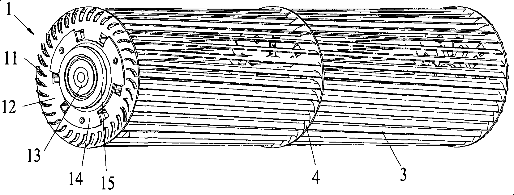
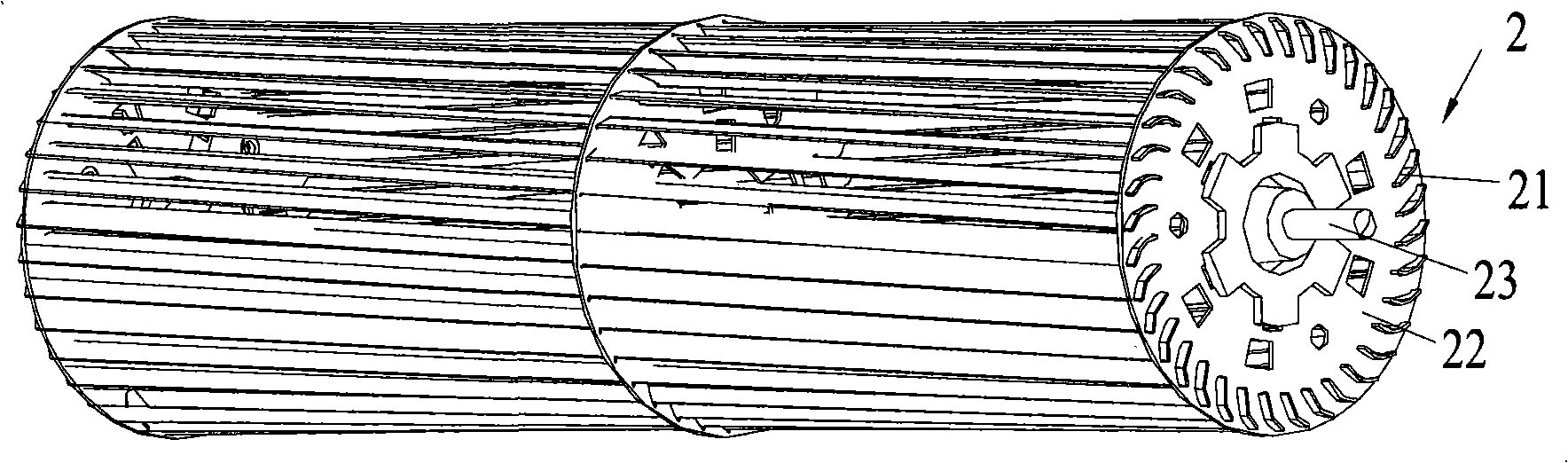
[0020] Such as figure 1 and figure 2 As shown, the cross-flow fan of the present invention includes: a first rotary bracket 1, a second rotary bracket 2, and fan blades 3, wherein the first rotary bracket 1 and the second rotary bracket 2 are arranged to have a common axis of rotation, and more A plurality of blades 3 are inserted between the first rotating bracket 1 and the second rotating bracket 2 and arranged in a cylindrical structure around the common rotation axis, that is, a plurality of blades 3 are arranged around the rotation axis of the cross-flow fan. Since the fan blades 3 are interspersed with the first rotary bracket 1 and the second rotary bracket 2 , each fan blade 3 is a detachable part.

[0021] see further figure 1 and figure 2 , the first rotary bracket 1 is a first blade positioning ring 12 provided with a rotary support member, the first blade positioning ring 12 is provided with a plurality of sockets 11 along the circumferential direction, and th...


PUM


Abstract

The invention provides a cross-flow fan comprising a first rotary support, a second support and blades. The first rotary support and the second support are respectively provided with a plurality of jacks, and the plurality of jacks are arranged around a common rotary axial line; and the blades are detachably inserted between the first rotary support and the second support through matching with the jacks, wherein the plurality of blades are arranged by surrounding the rotary axial line to form a barrel structure. According to the cross-flow fan disclosed by the invention, the blades and other assemblies are detachably assembled, thus the manufacturing is simplified and the development cycle is shortened.

Description

technical field [0001] The invention relates to a cross-flow fan. Background technique [0002] At present, the fan is integrally injection-molded in the form of injection molding. The fan is injection molded through the injection molding process and then welded together by butt welding. For example, the patent "Cross-flow fan and its manufacturing method and device" with publication number CN1118844A discloses a cross-flow fan in which the multi-blade impeller is integrally formed, so the development period is long and it is inconvenient to manufacture. Contents of the invention [0003] In view of the problems existing in the related art, the object of the present invention is to provide a cross-flow fan, which is convenient for manufacture and shortens the development period. [0004] To achieve the above object, the present invention provides a cross-flow fan, which includes a first rotary bracket and a second rotary bracket, each having a plurality of sockets arrang...

Claims


Application Information

Patent Timeline
Patent Type & Authority Applications(China)
IPC IPC(8): F04D17/04F04D29/60
CPCF04D17/04F04D29/626
Inventor 张守信付裕张立智刘志强
Owner HAIER GRP CORP
Why Eureka
Try Eureka