
Arching formwork erecting method for assembled framework beam plate

A formwork support method and a frame beam technology, which are applied to the joints of formwork/formwork/work frame, formwork/formwork/work frame, and on-site preparation of building components, which can solve the problem of increased leveling engineering and constant load of beams and slabs increase, increase in the amount of floor leveling works, etc.

Inactive Publication Date: 2013-04-17
重庆建工建筑产业技术研究院有限公司 +1
View PDF6 Cites 0 Cited by
  • Summary
  • Abstract
  • Description
  • Claims
  • Application Information

AI Technical Summary

Problems solved by technology

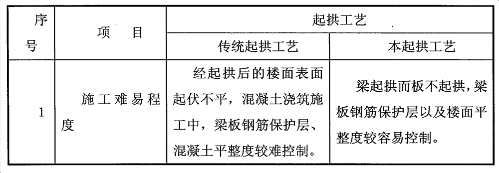
[0006] However, the traditional arching technology brings the following problems to different degrees: (1) When using traditional construction technology for construction: the general method is to erect the frame first according to the design beam bottom elevation, and then install the bottom formwork according to 1‰~3‰ arching, resulting in construction The floor elevation exceeds the designed structural elevation, and the excess value is the value of the arching height (2) Since the slab is arched together with the beam, not only the direction of the arching of the slab is wrong, the value of the arching is too large, but also the amount of leveling work on the floor is increased , the cost increases (3) The increase in the amount of floor leveling will cause an additional increase in the dead load of the beam and slab, which is unfavorable to the structural force

Method used


Image

  • Arching formwork erecting method for assembled framework beam plate
  • Arching formwork erecting method for assembled framework beam plate
  • Arching formwork erecting method for assembled framework beam plate

Examples


Embodiment Construction

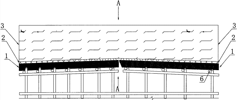
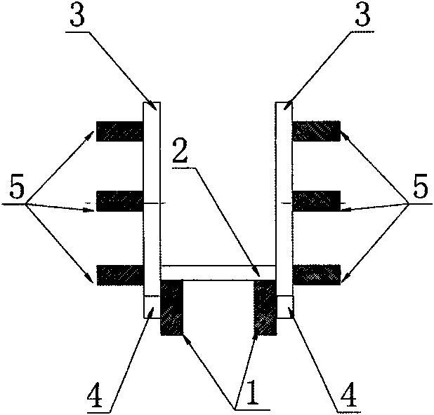
[0032] A method for arching and supporting formwork of a prefabricated frame beam slab, comprising the following steps:

[0033] (1) Foundation engineering: determine the span value between the corresponding beam supports, the construction arch height, the elevation of the beam bottom, the elevation of the top of the beam, and the elevation of the floor, build the beam support frame, and erect a group on the beam support frame, etc. Horizontal connecting rods 6 with parallel spacing, wherein the beam support frame includes a cross bar, a vertical rod and an adjustable base;

[0034] (2) Install a group of beam bottom corrugations 1 on the horizontal connecting rod 6, and fixedly install the beam bottom formwork 2 on the beam bottom corrugation 1. , Beam bottom flute 1 on the lower right side; adjust the height of the beam support frame and each horizontal connecting rod 6 through the adjustable base, until the beam bottom flute 1 and the beam bottom formwork 2 realize the foll...


PUM


Abstract

The invention discloses an arching formwork erecting method for an assembled framework beam plate. The method comprises the following steps of: constructing a beam formwork bracket, arranging a beam bottom edge and a beam bottom template on the beam formwork bracket, and splicing beam side templates at two sides of the beam bottom template, wherein the beam bottom template is transited from high to low between a mid-span position and a beam support position through an adjusting seat of the beam formwork bracket, the elevation of the mid-span position of the upper surface of the beam bottom template is matched with the elevation of a beam bottom, the difference between the elevation of the upper surface of the beam bottom template at the beam support position and the elevation of the mid-span position is a construction arching height, and the elevation of the upper opening of the beam side template is matched with the elevation of a beam top; and performing floor formwork erection, pouring a beam, separately leveling the beam top, and finishing leveling of the floor. By using the arching formwork erecting method for the assembled framework beam plate, the elevation of the beam bottom is changed, the elevation of the beam top is unchanged, the elevation of the floor is unchanged under the condition of keeping the thickness of the floor unchangeable, the elevation of a building floor structure can be effectively controlled, and the leveling workload is further reduced.

Description

technical field [0001] The invention belongs to an arching formwork method for constructing a load-bearing floor slab that is wholly or partly formed on site by casting or a similar method, and in particular relates to an arching formwork method for an assembled frame beam slab. Background technique [0002] In order to avoid the sagging of the beam bottom due to the decline of the formwork support under the load-bearing compression during construction and to offset the effect of appearance parallax, the "Code for Construction Acceptance of Concrete Structure Engineering (GB50204-92 Regulations)" stipulates that cast-in-place reinforced concrete beams and slabs, when the span is equal to and When it is greater than 4m, the formwork should be arched. When there is no specific requirement in the design, the arched height should be 1 / 1000-3 / 1000 of the full span length. [0003] Formwork arching is divided into two types: design arching and construction arching. Design arching:...

Claims


Application Information

Patent Timeline
Patent Type & Authority Patents(China)
IPC IPC(8): E04G13/04E04G11/36E04G17/00
Inventor 邓祖祥田小强曾强白瑞华邓万敏钟鸣
Owner 重庆建工建筑产业技术研究院有限公司
Learn More