


Quick Research
Generate reliable direction feasibility study reports for your R&D in just a few steps.

Technical Q&A
Discover and master advanced knowledge NOW. Basics, ideas, possibilities, all at once.

Find Solutions
As an expert in R&D theories, this can generate solutions to your technical problems instantly.

Evaluate Feasibility
Analyze your overall solution with one click, know your potential R&D risks in advance.

Monitor Landscape
Get weekly tech updates, stay abreast of the latest tech innovations and key insights.
Indicator for displaying battery freshness
A fresh and battery-friendly technology, applied in the field of tracking the state of battery modules, can solve problems such as high cost
- Summary
- Abstract
- Description
- Claims
- Application Information
AI Technical Summary
Problems solved by technology
Method used
Image

Examples
Embodiment Construction
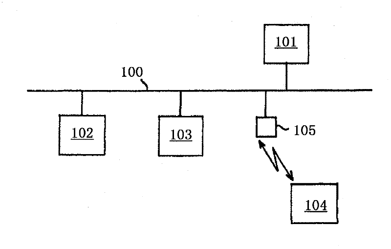
[0024] figure 1 Represents a fieldbus system, which includes a fieldbus 100 , a programmable logic controller 101 and three field devices 102 , 103 and 104 connected to the fieldbus 100 . Field device 104 is a battery-operated field device which has communication components for wireless data exchange with transceiver unit 105 connected to field bus 100 . This wireless connection of the field devices to the fieldbus system simplifies the installation of the field devices.
[0025] In the case of battery-operated field devices and communication components, it is important to replace the battery module of the respective device in good time in order to avoid a sudden interruption of the operation of the field device or communication component. Batteries for supplying the field devices and communication components are packaged in such a way that the packaging must be destroyed before use. In order to keep track of the battery status, it is possible, for example, to reset consumpt...
PUM
 Abstract
Description
Claims
Application Information
 - R&D Engineer
- R&D Manager
- IP Professional
- Industry Leading Data Capabilities
- Powerful AI technology
- Patent DNA Extraction
Browse by: Latest US Patents, China's latest patents, Technical Efficacy Thesaurus, Application Domain, Technology Topic, Popular Technical Reports.
© 2024 PatSnap. All rights reserved.Legal|Privacy policy|Modern Slavery Act Transparency Statement|Sitemap|About US| Contact US: help@patsnap.com