Tooth implant

An implant and dental implant technology, applied in dental implants, dentistry, prosthetics, etc., can solve problems such as inflammation and achieve the effect of good human body compatibility

Active Publication Date: 2011-11-16
MEHROF IMPLANT TECH GMBH
View PDF10 Cites 12 Cited by
  • Summary
  • Abstract
  • Description
  • Claims
  • Application Information

AI Technical Summary

Problems solved by technology

[0003] In the connection between the distal implant and the proximal implant, there is the problem that, due to the different manufacture, bacteria can get in there and accumulate more or less in large quantities, which can cause inflammation, for example

Method used


Image

  • Tooth implant
  • Tooth implant
  • Tooth implant

Examples


Embodiment Construction

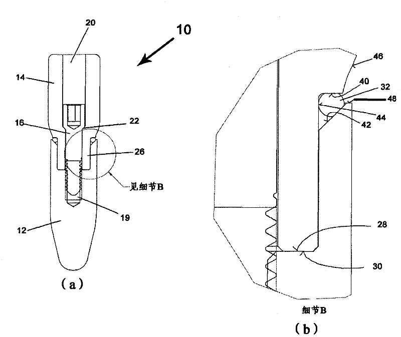
[0064] figure 1 A first variant of a two-part dental implant 10 is shown. The two-part dental implant comprises a distal implant part 12, also called a distal stem, which forms the artificial tooth root of the dental implant 10, also called a root stem.

[0065] Furthermore, the dental implant 10 comprises a proximal implant portion 14, also referred to as a proximal stem or construct stem. The proximal implant portion 14 is used to receive an artificial dental crown (not shown).

[0066] like figure 1 As shown in a, the distal implant part 12 and the proximal implant part 14 are connected to each other by stud bolts 16 and are in a fully assembled state. For this purpose, in the distal implant part 12, an internally threaded blind hole 18 is provided. The blind hole 18 extends along the central longitudinal axis of the distal implant portion 12 .

[0067] In the proximal implant part 14 a stepped longitudinal hole 20 is provided along the longitudinal axis of the proxi...


PUM


Abstract

The invention relates to a multi-part tooth implant with at least a proximal implant part and a distal implant part that are to be connected to each other such that a connection site is obtained when the two implant parts are in the connected state. An annular sealing element is arranged at this connection site and, in the fitted state of the tooth implant, is clamped between mutually opposite sealing surfaces, namely a sealing surface of the proximal implant part and a sealing surface of the distal implant part, such that the sealing element has an outer surface portion that forms part of the outer contour of the tooth implant. The two sealing surfaces initially approach each other in a direction oriented outwards from a central longitudinal axis of the tooth implant. The sealing surfaces merge into outer surfaces of the tooth implant at the place where, in the outer contour of the fitted tooth implant, a surface portion formed by the sealing element in each case adjoins a surface portion formed by the respective implant part. These outer surfaces move away from each other in the outwardly oriented diretion.

Description

technical field [0001] The invention relates to a multi-part dental implant having at least a proximal implant part and a distal implant part connectable to each other, forming a connection part when the two implant parts are in a connected state. An annular seal is provided between the two implants. Background technique [0002] Dental implants of this type are known, for example, from DE 20 2005 015 074, DE 299 24 510 or US 4,756,689. In all these cases, the distal implant serves as an artificial tooth root that can be screwed into place in the jawbone before connecting the proximal implant and possibly other implants to the distal implant . The proximal implant is usually used as the construct stem and supports the artificial crown. In many cases, the distal and proximal implants are connected to each other by a cylindrical screw. [0003] In the connection between the distal implant part and the proximal implant part, there is the problem that, due to the different m...

Claims


Application Information

Patent Timeline
Patent Type & Authority Applications(China)
IPC IPC(8): A61C8/00
CPCA61C8/005A61C8/0086A61C8/0059
Inventor 于尔根·莫霍夫
Owner MEHROF IMPLANT TECH GMBH
Why Eureka
Try Eureka