Fatigue test loading device of transportation on bridge
A fatigue test and loading device technology, which is applied in the testing of measuring devices, machine/structural components, and the use of stable tension/pressure to test the strength of materials, etc., can solve the problems of high height of moving parts, high center of gravity, and high equipment cost, Achieve the effect of improving accuracy and experimental efficiency, easy transportation and installation, and good operation stability
- Summary
- Abstract
- Description
- Claims
- Application Information
AI Technical Summary
Problems solved by technology
Method used
Image
Examples
Embodiment 1
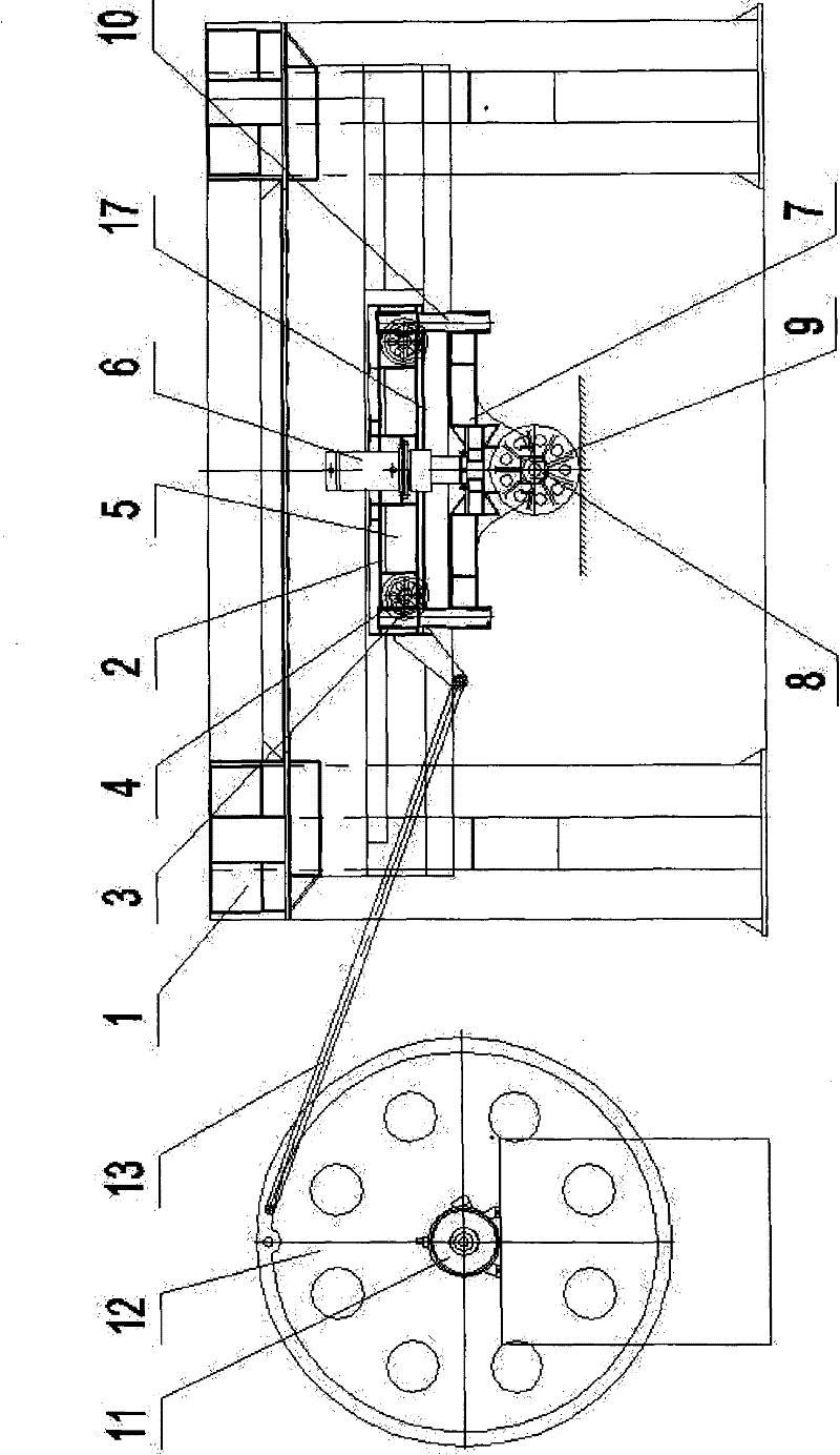
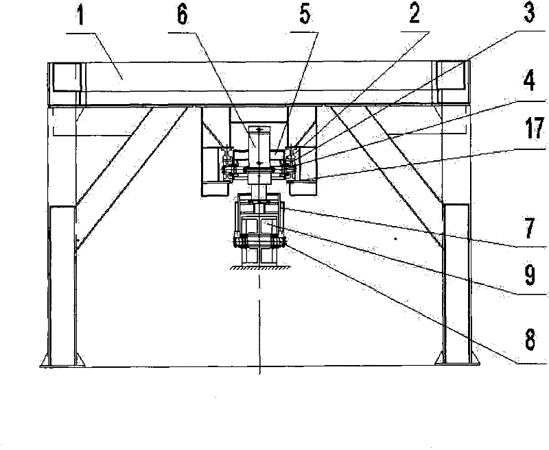
[0027] as attached figure 1 , 2 As shown, a loading device for a bridge running fatigue test of the present invention has a structure comprising a main frame 1, two mutually parallel loading rails 2 are horizontally arranged above the main frame 1, and the bottoms of the two parallel loading rails 2 are provided with Two pairs of loading wheels 3, each pair of loading wheels 3 are connected by a loading shaft 4, and the loading shafts 4 are all arranged on the upper support frame 5, and the middle part of the upper support frame 5 is connected with the oil cylinder body of the double-acting oil cylinder 6, and the double-acting The piston rod of the oil cylinder 6 is connected with the lower support frame 7, and the lower support frame 7 is provided with a rolling assembly; the above-mentioned rolling assembly includes a rolling shaft 8 and a rolling wheel 9, the rolling wheel 9 is a steel wheel, and the rolling wheel 9 is arranged in the middle of rolling axle 8, and rolling...
Embodiment 2
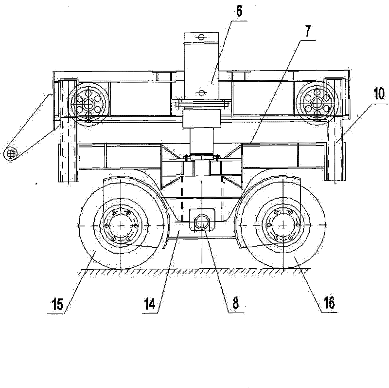
[0032] as attached image 3 As shown, a loading device for a bridge running fatigue test of the present invention has a structure comprising a main frame 1, two mutually parallel loading rails 2 are horizontally arranged above the main frame 1, and the bottoms of the two parallel loading rails 2 are provided with There are two pairs of loading wheels 3 , and an unloaded track or an unloaded support frame 17 is also arranged below the above two pairs of loading wheels 3 . Each pair of loading wheels 3 is connected by a loading shaft 4, and the loading shafts are all arranged on the upper support frame 5, and the middle part of the upper support frame 5 is connected with the oil cylinder body of the double-acting oil cylinder 6, and the piston rod of the double-acting oil cylinder is connected with the lower support The frame 7 is connected, and the lower support frame 7 is provided with a rolling assembly; the above-mentioned rolling assembly includes a rolling shaft 8, a conve...
PUM
 Abstract
Description
Claims
Application Information
 - R&D
- Intellectual Property
- Life Sciences
- Materials
- Tech Scout
- Unparalleled Data Quality
- Higher Quality Content
- 60% Fewer Hallucinations
Browse by: Latest US Patents, China's latest patents, Technical Efficacy Thesaurus, Application Domain, Technology Topic, Popular Technical Reports.
© 2025 PatSnap. All rights reserved.Legal|Privacy policy|Modern Slavery Act Transparency Statement|Sitemap|About US| Contact US: help@patsnap.com


