
Frequency-beating device for laser frequency measurement

A frequency measurement and laser technology, applied in the field of optoelectronics, which can solve the problems of insufficient triggering of frequency counter readings, decreased signal-to-noise ratio of beat frequency signals, and low signal-to-noise ratio of beat frequency signals.

Active Publication Date: 2011-11-16
BEIJING CHANGCHENG INST OF METROLOGY & MEASUREMENT AVIATION IND CORP OF CHINA
View PDF2 Cites 13 Cited by
  • Summary
  • Abstract
  • Description
  • Claims
  • Application Information

AI Technical Summary

Problems solved by technology

However, in the actual measurement of optical frequency, the energy of the frequency comb teeth involved in the beat frequency in the femtosecond optical comb is extremely weak, so the common measurement method will encounter two problems: a) The signal-to-noise ratio of the beat frequency signal gradually decreases with time, and the frequency comb involved The time for the two light sources of the beat frequency to maintain the coincidence of spatial paths and the same polarization direction is relatively short, which is not conducive to the need for long-term frequency measurement; b) The signal-to-noise ratio of the beat frequency signal is not high enough to trigger the reading of the frequency counter
The existence of these two problems seriously restricts the further development of femtosecond optical combs to measure optical frequencies.

Method used


Image

  • Frequency-beating device for laser frequency measurement
  • Frequency-beating device for laser frequency measurement

Examples


Embodiment

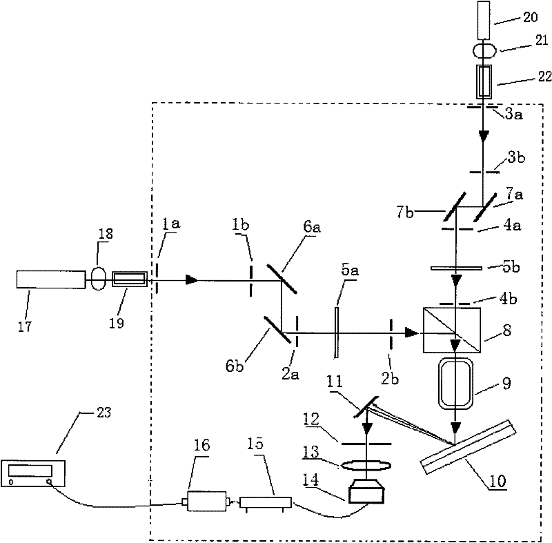
[0031] A beat frequency device for laser frequency measurement, such as figure 1 As shown, it includes the first collimation and positioning pinhole diaphragm, the second collimation and positioning pinhole diaphragm, the third collimation and positioning pinhole diaphragm, the fourth collimation and positioning pinhole diaphragm, the fifth collimation and positioning pinhole diaphragm Aperture diaphragm, the sixth collimation and positioning pinhole diaphragm, the seventh collimation and positioning pinhole diaphragm, the eighth collimation and positioning pinhole diaphragm, the first total reflection mirror, the second total reflection mirror, the third total reflection mirror, the fourth total reflection mirror, the first half-wave plate, the second half-wave plate, polarizing beam splitter, Glan prism, grating, silver mirror, ninth aperture diaphragm with adjustable aperture, focusing lens, avalanche diode, Low-noise amplifier, band-pass filter, one-dimensional mobile plat...


PUM


Abstract

The invention relates to a frequency-beating device for laser frequency measurement, which belongs to the technical field of photoelectrons and comprises a first collimation positioning aperture diaphragm, a second collimation positioning aperture diaphragm, a third collimation positioning aperture diaphragm, a fourth collimation positioning aperture diaphragm, a fifth collimation positioning aperture diaphragm, a sixth collimation positioning aperture diaphragm, a seventh collimation positioning aperture diaphragm, an eighth collimation positioning aperture diaphragm, a first totally-reflecting mirror, a second totally-reflecting mirror, a third totally-reflecting mirror, a fourth totally-reflecting mirror, a first half-wave plate, a second half-wave plate, a polarization light-splittingprism, a Glan prism, a raster, a silver mirror, a ninth adjustable-aperture aperture diaphragm, a gathering lens, an avalanche diode, a low-noise amplifier, a band-pass filter, a one-dimensional mobile platform and a vibration isolation optical panel. The frequency-beating device disclosed by the invention is easy to regulate and maintain a frequency-beating optical path, and can achieve the purpose of improving a signal to noise ratio of a frequency-beating signal so as to be convenient for reading by using a frequency counter and keeping the high signal to noise ratio frequency-beating signal for a long time.

Description

technical field [0001] The invention relates to a beat frequency device for laser frequency measurement, in particular to a beat frequency device for measuring light frequency by using a femtosecond optical comb, which belongs to the field of optoelectronic technology. Background technique [0002] The related research of femtosecond optical comb won the Nobel Prize in Physics in 2005. Since then, femtosecond optical comb technology has made revolutionary progress in optical frequency measurement. When using a femtosecond optical comb to measure the optical frequency, it is necessary to obtain the repetition frequency f of the femtosecond optical comb at the same time rep , Carrier envelope phase shift frequency f ceo And the frequency f of the beat frequency signal between the femtosecond optical comb and the optical frequency to be measured beat . [0003] Measurement repetition frequency f rep Phase-shifted frequency f from the carrier envelope ceo can be directly ob...

Claims


Application Information

Patent Timeline
IPC IPC(8): G01J9/04
Inventor 张大鹏韩海年梁志国叶蓬魏志义严家骅张志权武腾飞
Owner BEIJING CHANGCHENG INST OF METROLOGY & MEASUREMENT AVIATION IND CORP OF CHINA
Learn More