
Maglev molecular pump, and control method and manufacturing method thereof

A control method and molecular pump technology, applied in pump control, pump, axial flow pump, etc., can solve problems such as complex rotor motion, long adjustment time, and complicated control process, so as to improve control efficiency and stability and reduce control Difficulty, the effect of simplifying the control process

Active Publication Date: 2011-11-16
KYKY TECH +1
View PDF5 Cites 14 Cited by
  • Summary
  • Abstract
  • Description
  • Claims
  • Application Information

AI Technical Summary

Problems solved by technology

[0006] The technical problem to be solved by the present invention is that in the prior art, since the center of mass of the rotor is set between the first radial magnetic bearing and the second radial magnetic bearing, the movement of the rotor is complicated when the rotor is affected by the disturbance force and produces translation and rotation at the same time , it is difficult to adjust the parameters of the magnetic bearing, the control process is complex, the required adjustment time is long, and the technical problems are low efficiency. However, it is necessary to provide a method that can make the rotor move in both translation and rotation when the rotor is in translation and rotation at the same time. The magnetic levitation molecular pump, its control method and manufacturing method are basically decoupled from each other, greatly simplify the control process of the magnetic levitation molecular pump, reduce the difficulty of control, and improve the control efficiency and stability of the magnetic levitation molecular pump system

Method used


Image

  • Maglev molecular pump, and control method and manufacturing method thereof
  • Maglev molecular pump, and control method and manufacturing method thereof
  • Maglev molecular pump, and control method and manufacturing method thereof

Examples


Embodiment Construction

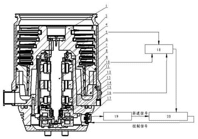
[0020] Such as figure 1 Shown is a schematic structural diagram of the magnetic levitation molecular pump involved in the present invention. In this embodiment, the magnetic levitation molecular pump is arranged vertically, and the magnetic levitation molecular pump includes a pump body 3 and a rotor shaft arranged in the pump body 3 System, and other structures that the magnetic levitation molecular pump described in the prior art should have. Since the present invention does not involve the above-mentioned other structures, it will not be repeated here.

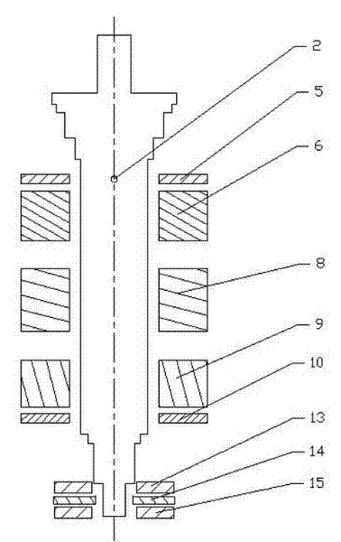
[0021] The rotor shaft system includes a rotor, a first radial magnetic bearing 6, a second radial magnetic bearing 9, a first axial magnetic bearing 13 and a second axial magnetic bearing 15; the rotor includes a rotor shaft 7, and The impeller 1 to which the rotor shaft 7 is fixed, and the assembly parts for fixing the impeller 1, such as screws, nuts, and the like.

[0022] The axis of the rotor shaft 7 is arranged in a verti...


PUM


Abstract

The invention discloses a maglev molecular pump, and a control method and a manufacturing method thereof. The maglev molecular pump comprises a pump body and a rotor shaft system arranged in the pump body. The rotor shaft system comprises a rotor, a first radial magnetic bearing, a second radial magnetic bearing, a first axial magnetic bearing and a second axial magnetic bearing. The rotor comprises a rotor shaft and an impeller fixed with the rotor shaft. The first radial magnetic bearing and the second radial magnetic bearing are sequentially sleeved in the middle of the rotor shaft at intervals. Under a normal state, the mass centre of the rotor is arranged on the axis of the rotor shaft and superposed with the mass centre of a first radial sensor. According to the maglev molecular pump disclosed by the invention, the situation that two motions of translation and rotation of the rotor are mutually decoupled is realized basically; the two motions can be adjusted and controlled respectively; therefore, the control process is simplified; the control difficulty is reduced; and the control efficiency and the stability of a maglev molecular pump system are improved.

Description

Technical field [0001] The invention relates to the technical field of vacuum obtaining equipment, in particular to a magnetic levitation molecular pump and its control method and manufacturing method. Background technique [0002] Molecular pump is a kind of vacuum pump, which uses high-speed rotating rotor impeller to transfer momentum to gas molecules to obtain directional speed, so that the gas is compressed, driven to the exhaust port, and then sucked by the fore-stage pump . Magnetic levitation molecular pump is a molecular pump that uses magnetic bearings (also known as active magnetic bearings) as the molecular pump rotor support. It uses magnetic bearings to stably suspend the rotor in the air, so that there is no mechanism between the rotor and the stator during high-speed operation. Contact has the advantages of no mechanical wear, low energy consumption, high allowable speed, low noise, long life, and no need for lubrication. At present, magnetic levitation molecular...

Claims


Application Information

Patent Timeline
Patent Type & Authority Applications(China)
IPC IPC(8): F04D19/04F04D27/00
Inventor 张剀武涵李奇志张小章邹蒙
Owner KYKY TECH
Learn More