Loose-preventing structure of automatic cutter releasing pulling mechanism

A broach loosening and anti-loosening technology, applied in the accessories of broaching machine, broaching machine, metal processing equipment, etc., can solve the problems of affecting cutting effect, decrease of broaching force, loosening, etc., and achieve the effect of simple structure

Inactive Publication Date: 2011-11-16
无锡桥联数控机床有限公司
View PDF6 Cites 5 Cited by
  • Summary
  • Abstract
  • Description
  • Claims
  • Application Information

AI Technical Summary

Problems solved by technology

In this structure, since the spindle needs to perform high-speed forward and reverse movement during the machining process, the threaded conne...

Method used


Image

  • Loose-preventing structure of automatic cutter releasing pulling mechanism
  • Loose-preventing structure of automatic cutter releasing pulling mechanism

Examples


Embodiment Construction

[0010] The present invention will be further described below in conjunction with the embodiments in the accompanying drawings.

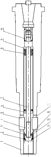
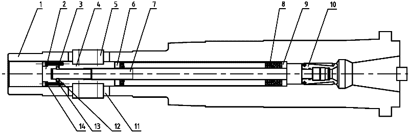
[0011] figure 1 , including main shaft 1, gland 2, semi-circular ring 3, transition shaft 4, key 5, washer 6, pull rod 7, spring set 8, washer 9, claw 10, keyway 11, semi-circular ring installation groove 12, inner Step 13, screw 14 etc.

[0012] Such as figure 1 As shown, the present invention is an anti-loosening structure for the automatic broach loosening mechanism of numerical control equipment, including a transition shaft 4 installed in a hollow main shaft 1 and a pull rod 7 threaded with the transition shaft 4 . The main shaft 1 is provided with two symmetrical key slots 11 communicating with the hollow hole, and the transition shaft 4 is fixed with two keys 5 passing through the two key slots 11 and protruding outside by screws. The key 5 is driven by a hydraulic cylinder or a booster cylinder, and can move axially in the key groove 11. ...


PUM


Abstract

The invention relates to a loos-preventing structure used for numeric control equipment automatic cutter releasing pulling mechanism, and the loos-preventing structure comprises a transition shaft arranged in a hollow spindle and a pull rod which is in threaded connection with the transition shaft, wherein the spindle is provided with a key slot, the transition shaft is provided with a key which penetrates through the key slot and can axially move in the key slot, and a spring assembly is arranged between the inner end of the transition shaft and the inner step of the spindle; and the pull rod is in threaded connection with the interior of the transition shaft and penetrates through the transition shaft, the pull rod arranged at one side of the outer end of the transition shaft is provided with a semi-ring mounting slot, the semi-ring mounting slot is internally provided with a semi ring, and the outer end of the transition shaft is provided with a gland used for fixing the semi ring at a mounting position. In the invention, the semi ring is arranged on the pull rod, the locations of the pull rod and the transition shaft are fixed, the length of threaded connection of the pull rodand the transition shaft is maintained constant, and the phenomenon that the cutter pulling force of the spindle is reduced as the threaded connection of the pull rod and the transition shaft is loosened can be prevented.

Description

technical field [0001] The invention relates to an automatic broach loosening mechanism for a main shaft in a large-scale numerical control device, in particular to an anti-loosening structure of the automatic broach loosening mechanism. Background technique [0002] The automatic loosening and broaching mechanism of the spindle in large-scale numerical control equipment mainly completes the functions of automatically changing the attachment head and processing tools. Existing automatic broach loosening mechanism is mainly made up of main shaft, transition shaft, pull rod, spring group etc., is threadedly connected between transition shaft and pull rod, and transition shaft is provided with release key. The spring group is used to provide the broaching force, and the release button is driven by a hydraulic cylinder or a booster cylinder to complete the release action. In this structure, since the spindle needs to perform high-speed forward and reverse movement during the m...

Claims


Application Information

Patent Timeline
IPC IPC(8): B23B19/02B23D39/00
Inventor 汤彩萍刘江杨凌云高晓军周晖
Owner 无锡桥联数控机床有限公司
Why Eureka
Try Eureka