
Electrical connector system

An electrical connector system and technology of electrical connectors, which are applied in the direction of connection, parts of connection devices, circuits, etc., can solve the problems of large space occupied by built-in circuit boards, unsatisfactory electrical performance, and high cost of connectors, etc., to achieve The effect of reducing occupied area, improving electrical performance and increasing production efficiency

Inactive Publication Date: 2014-02-19
FOXCONN (KUNSHAN) COMPUTER CONNECTOR CO LTD +1
View PDF6 Cites 3 Cited by
  • Summary
  • Abstract
  • Description
  • Claims
  • Application Information

AI Technical Summary

Problems solved by technology

In the traditional design mentioned above, the inductance and capacitance are set separately, the circuit is long, the electrical performance is not ideal, and it takes up a lot of space on the built-in circuit board, which is more labor-intensive in actual production, resulting in a higher cost of the connector

Method used


Image

  • Electrical connector system
  • Electrical connector system
  • Electrical connector system

Examples


Embodiment Construction

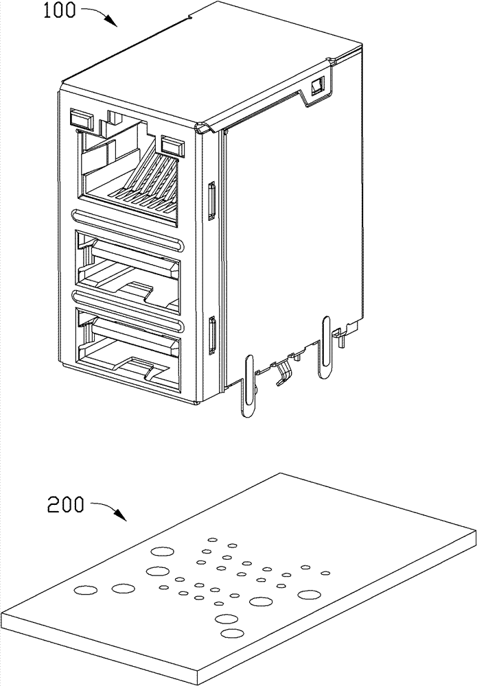
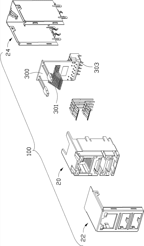
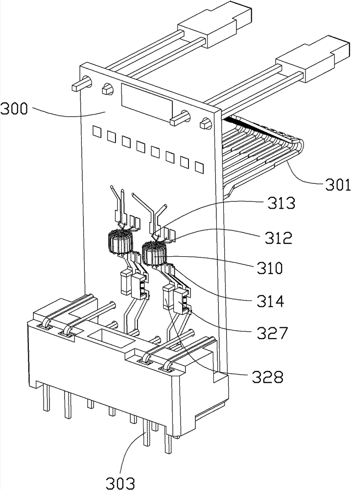
[0013] see Figures 1 to 6 , which shows an electrical connector system for network transmission according to the present invention. The electrical connector system has two or more network signal channels, which includes an electrical connector 100 that can be matched with a mating connector (not shown) and an external circuit board 200 for loading the electrical connector 100. The electrical connector 100 also includes an insulating body 20 capable of accommodating the above-mentioned docking connector, a built-in circuit board 300 disposed in the insulating body 20, two transformers 310 installed on the built-in circuit board 300, and a filter connecting the two transformers 310 respectively. structure, and the metal shells 22 and 24 covering the outside of the insulating body 20 .

[0014] Each transformer 310 includes a first coil 312 and a second coil 314 coupled to each other.

[0015] Each filter structure includes a common-mode suppression module 327 and a first modu...


PUM


Abstract

An electrical connector system possesses an inductance and a capacitance, wherein the inductance and the capacitance have a filtering effect. The inductance and the capacitance are integrated and designed as one assembly. The assembly in the network power connector system occupies small area, has a short inductance capacitance loop, good electrical property and low costs. The electrical connector system is convenient for production.

Description

【Technical field】 [0001] The invention relates to an electrical connector system for network transmission, in particular to a filter structure of the electrical connector system. 【Background technique】 [0002] In traditional electrical connector products with a transformer module and a common mode suppression module, the usual practice is to set the transformer module and the common mode suppression coil as a whole, and then install them on the built-in circuit board of the electrical connector, and set the inductance and capacitance separately , and finally transferred to the external circuit board. In the traditional design mentioned above, the inductance and capacitance are set separately, the circuit is long, the electrical performance is not ideal, and it takes up a lot of space on the built-in circuit board, which is more labor-intensive in actual production, resulting in a higher cost of the connector. [0003] Therefore, it is necessary to improve the existing tech...

Claims


Application Information

Patent Timeline
Patent Type & Authority Patents(China)
IPC IPC(8): H01R13/719H01R13/66H01R12/70
Inventor 徐勇春
Owner FOXCONN (KUNSHAN) COMPUTER CONNECTOR CO LTD
Learn More