Eureka AIR delivers breakthrough ideas for toughest innovation challenges, trusted by R&D personnel around the world.

Main and backup line switching system for radio frequency adapter and transmitter and implementation method thereof

A technology for switching systems and transmitters, applied in transmission systems, signal transmission systems, instruments, etc., can solve the problems of failure to know the operating status of remote equipment in time, complex surrounding environment, unattended, etc., and achieve good real-time response and processing capacity, saving human resources, and overcoming the effect of wide distribution

Active Publication Date: 2011-11-02
CHENGDU CHITONG DIGITAL SYST
View PDF3 Cites 10 Cited by
  • Summary
  • Abstract
  • Description
  • Claims
  • Application Information

AI Technical Summary

Problems solved by technology

At present, there are several shortcomings in the management of transmitters in radio and television in various places: (1) Transmitters are distributed in urban and rural areas, and the traditional manual inspection method can no longer meet the needs of rapid network development; (2) Lack of professional maintenance Staff, maintainers are of varying levels
Maintenance personnel cannot keep abreast of the operating status and failure phenomena of remote equipment in time, and cannot troubleshoot equipment failures in time; (3) Due to the wide distribution of transmitters, most of them are in remote rural areas, the surrounding environment is complex and unattended, and effective maintenance of equipment Monitoring and monitoring are particularly important. The traditional main-backup switching mechanism of the transmitter does not involve the main-backup switching of the RF adapter.

Method used


Image

  • Main and backup line switching system for radio frequency adapter and transmitter and implementation method thereof
  • Main and backup line switching system for radio frequency adapter and transmitter and implementation method thereof

Examples


Embodiment

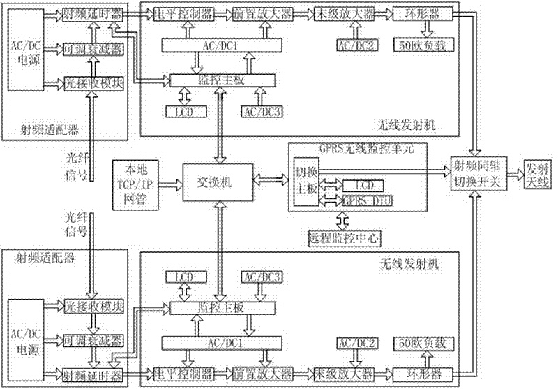
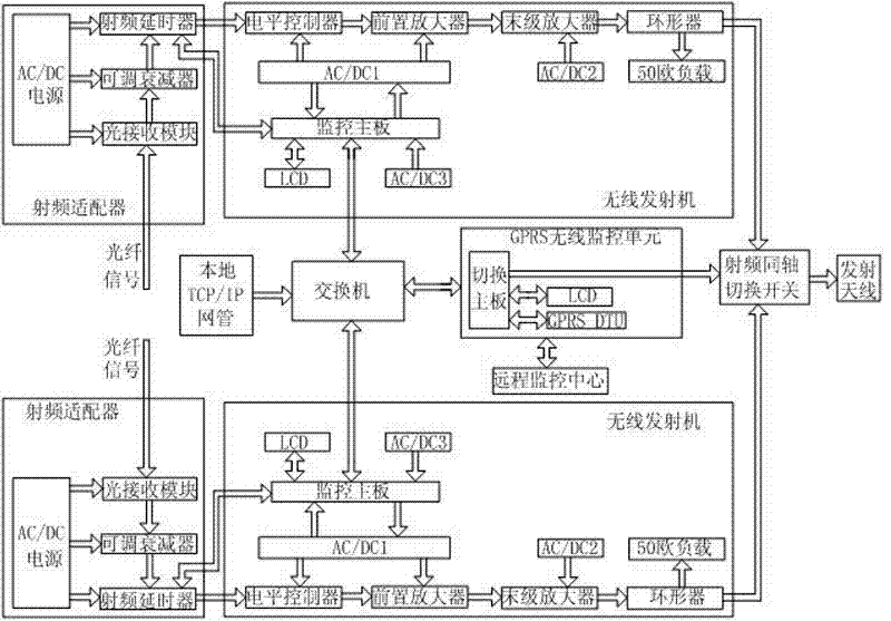
[0034] like figure 1 As shown, the radio frequency adapter and transmitter main backup switching system of the present invention includes two identical sets of equipment, both of which are mutual backups, each set of equipment includes a sequentially connected radio frequency adapter and a transmitter, and the radio frequency adapter includes sequentially connected The optical receiving module, adjustable attenuator, and radio frequency delayer also include AC / DC power supply, which is used to provide power for the optical receiving module, adjustable attenuator, and radio frequency delayer; the transmitter includes level controllers connected in sequence , preamplifier, final stage amplifier, circulator, also includes the feed system that provides power for the level controller, preamplifier, final stage amplifier, circulator, and monitoring main board; also includes GPRS wireless monitoring unit, radio frequency simultaneous Axis switching switch, switch, remote monitoring ...


PUM


Abstract

The invention discloses a main and backup line switching system for a radio frequency adapter and a transmitter and an implementation method thereof. Based on the characteristics of high speed and always online of the GPRS (general packet radio service) wireless communication technology and by means of a network, the switching between main and backup lines can be realized so that the equipment maintenance does not occupy the use time of users, the normal maintenance and overhaul of the equipment can be realized in the mode of switching between the main line and the backup line; a remote monitoring center monitors the parameters of each component of the system in real time through a GPRS wireless monitoring unit and sends control instructions to each component through the GPRS wireless monitoring unit so as to timely alarm and solve the problem. By the adoption of the invention, the traditionally manned patrol mode is changed, human resource is saved, and the problem that transmitters are widely distributed, mostly distributed in rural and remote areas with complicated surrounding environments and are in an unattended state can be overcome.

Description

technical field [0001] The invention relates to a DTMB single-frequency network and a wireless transmitting system of the single-frequency network, in particular to a radio frequency adapter and a main backup switching system of a transmitter and a realization method thereof. Background technique [0002] As DTMB became the mandatory standard for terrestrial TV signals in China's broadcasting industry on August 1, 2007, all digital TV system suppliers that provide video transmission equipment for China's broadcasting industry will adopt the digital video modulation intellectual property (IP) in this standard. The scale of SFN is getting larger and larger, and the maintenance difficulty and workload of SFN transmitters also increase accordingly. The intelligent and networked active-standby switching system for transmitting equipment will surely become the mainstream of the future radio and television transmitting system. [0003] The transmitter is an important part of the D...

Claims


Application Information

Patent Timeline
Patent Type & Authority Applications(China)
IPC IPC(8): H04B1/74H04B1/02G08C17/02
Inventor 赖欣傅历建鲍辉
Owner CHENGDU CHITONG DIGITAL SYST
Why Eureka
Eureka Blog
Learn More