Odometer calibrating device

A technology of calibration device and odometer, applied in measuring devices, instruments, etc., can solve the problems of small driving speed range, excessive circuit board size, large rotation speed error, etc., to increase the driving speed range, ensure rotation speed accuracy, peripheral The effect of circuit simplification

Inactive Publication Date: 2012-11-14
NANJING UNIV OF SCI & TECH
View PDF4 Cites 0 Cited by
  • Summary
  • Abstract
  • Description
  • Claims
  • Application Information

AI Technical Summary

Problems solved by technology

Its disadvantages are: 1) The main frequency of the AT89C51 single-chip microcomputer system is 12MHz, the processing speed is slow, and the driving speed range that can be accurately measured is small; 2) LED display circuits and membrane keyboards are used, and LED display tubes and membrane keyboards are easy to damage, and Its peripheral circuit design is complex, and many chips such as 82C79, 7404, 7448, 74154, 74245 are needed to form keyboard scanning and LED display circuits; 3) The same step angle is used when the motor rotates at low speed and high speed. The maximum speed required cannot be achieved. If a larger step angle is used, the speed error will be larger when rotating at low speed; 4) The chip is packaged in a dual in-line package, and the size of the circuit board is too large
[0004] In short, the odometer detection device in the prior art cannot meet the actual needs of vehicle odometer or vehicle inertial positioning and orientation navigation device odometer measurement

Method used


Image

  • Odometer calibrating device
  • Odometer calibrating device
  • Odometer calibrating device

Examples


Embodiment

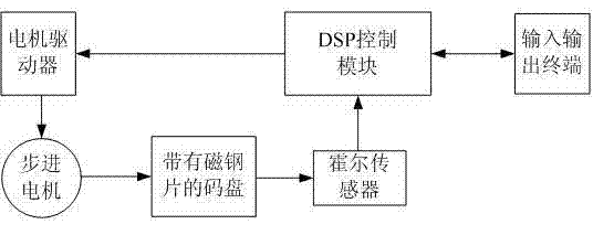
[0047] 1. The driving device is composed of a stepping motor, a motor driver, a code disc with a magnetic steel sheet, a Hall sensor, etc., which can drive the vehicle odometer or the odometer of the vehicle inertial positioning and directional navigation device to rotate at the set speed and direction;

[0048] 2. The control box is composed of DSP control circuit, touch screen, etc. It is used to set the motor speed and direction; control the start and stop of the odometer calibration device; control the acceleration and deceleration of the motor; display the speed and mileage.

[0049] The specific technical indicators of the odometer calibration device are as follows:

[0050] 1. The distance between the driving device and the control box is greater than 5 meters, and they are connected by a cable;

[0051] 2. The relationship between the number of revolutions and the mileage: 588.813 revolutions per kilometer;

[0052] 3. Display mileage (maximum): 200,000 meters, odo...


PUM


Abstract

The invention discloses an odometer calibrating device. A control box comprises a DSP (Digital Signal Processing) control module and an input / output terminal, wherein a code disk with a magnetic steel sheet is positioned on a rotary shaft of a stepping motor and is driven to rotate by the rotary shaft; a hall sensor is positioned beside the code disk with the magnetic steel sheet, is connected with the DSP control module and is used for transmitting a low-level pulse signal generated by a hall effect to the DSP control module; the DSP control module is connected with the stepping motor through a motor driver and is used for controlling the rotation of the stepping motor; and the DSP control module is connected with the input / output terminal. The odometer calibrating device can be used fordriving a vehicle odometer to rotate at a required running speed in a specified running speed range according to the transmission ratio of a vehicle output shaft, recording the running speed, calculating the road haul and verifying the functional accuracies of the vehicle odometer and a vehicle-mounted inertia positioning and orientating navigation device odometer.

Description

technical field [0001] The invention relates to a measurement verification device, in particular to an odometer verification device. Background technique [0002] With the development of our country's economy, various vehicles have been widely used in our life, so a detection device is needed to verify the accuracy of the vehicle odometer. [0003] The document "Design of Practical Odometer Detection Device for Vehicle System" (Du Xinni, Gao Qiang. Experimental Technology and Management, 2006, 23(6):37~39) introduces a design of vehicle system odometer detection device based on AT89C51 microcontroller. It is composed of motor drive circuit, mileage display circuit, keyboard scanning circuit and sensor circuit. Its disadvantages are: 1) The main frequency of AT89C51 single-chip microcomputer system is 12MHz, the processing speed is slow, and the driving speed range that can be accurately measured is small; 2) LED display circuit and membrane keyboard are used, and LED displa...

Claims


Application Information

Patent Timeline
Patent Type & Authority Patents(China)
IPC IPC(8): G01C25/00
Inventor 高强王力陈机林高伟季丽君侯远龙童仲志杜新妮
Owner NANJING UNIV OF SCI & TECH
Why Eureka
Try Eureka