Spiral-flow dryer

A dryer and swirling technology, applied in non-progressive dryers, dryers, drying solid materials, etc., can solve the problems of limited drying capacity, heat transfer area, complex structure, etc., and overcome the strict requirements of initial moisture content , intense heat and mass transfer, and low dust removal pressure

Active Publication Date: 2011-11-02
JIANGSU XIANFENG DRYING ENG
View PDF10 Cites 3 Cited by
  • Summary
  • Abstract
  • Description
  • Claims
  • Application Information

AI Technical Summary

Problems solved by technology

The above two utility models both use heat conduction to dry materials, so the drying capacity is limited by the heat transfer area of ​​the metal wall, and the structure is more complicated

Method used


Image

  • Spiral-flow dryer
  • Spiral-flow dryer
  • Spiral-flow dryer

Examples


Embodiment 1

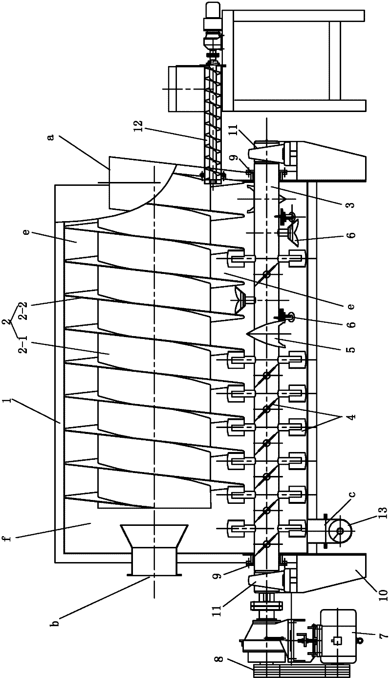
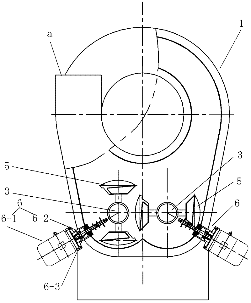
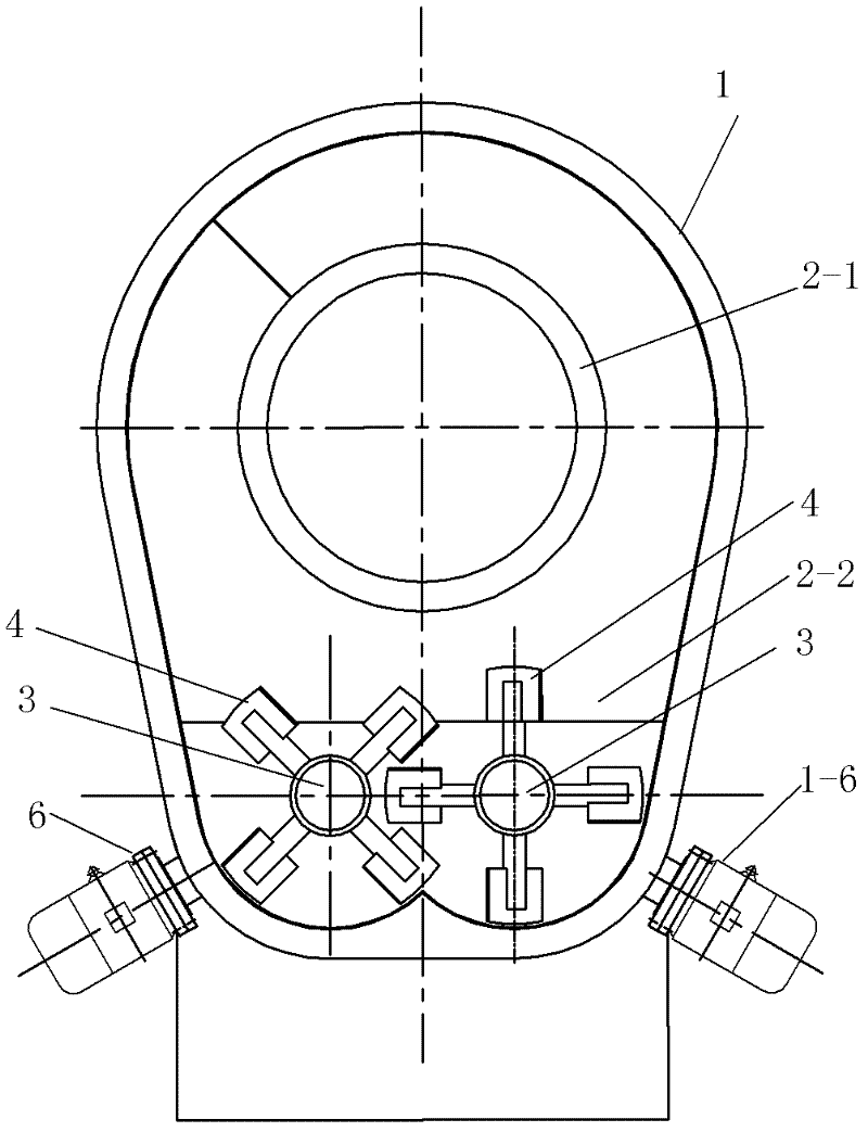
[0015] See Figure 1 to Figure 6 , the present embodiment has a body 1 supported by a frame 10, the upper part of the body 1 is arc-shaped, and the bottom is W-shaped. The upper part of the body cavity is provided with an air flow guide 2, and the space behind the body cavity and the air flow guide 2 is a swirl chamber f. The airflow guide 2 includes a core tube 2-1 and a spiral band 2-2 fixed on the core tube 2-1, and the spiral groove becomes a helical airflow channel e, and the rear end of the helical airflow channel e communicates with the settling chamber f, The airflow guide 2 is fixed by fixing the upper half edge of the spiral belt 2-2 on the inner wall of the body cavity.

[0016] The lower part of the body cavity is provided with a pair of stirring shafts 3, and the two stirring shafts 3 are respectively set corresponding to the two grooves at the bottom of the W shape. 9. The stirring shaft 3 is supported by a pair of bearing housings 11 fixed on the frame 10. The...


PUM


Abstract

The invention provides a spiral-flow dryer. An air flow guide-component is configured at the upper part of a dryer cavity. The air flow guide-component comprises a core tube and a spiral band fixed on the core tube. A spiral groove serves as a spiral air flow passage, and the rear end of the spiral air flow passage communicates with a rotational flow chamber. The edge of the upper half of the spiral band is fixed on the inner wall of the dryer cavity. A couple of mixer shafts are configured at the under part of the dryer cavity, and couples of paddle copy boards and coulters are configured on each of the mixer shafts. The invention expands the application scope of fluidized drying and is capable of breaking up and drying materials of shapes such as paste, slurry, granule, powder and filter cake inside the dryer. The invention is far superior to the common fluidized dryers in terms of volumetric drying intensity and can reduce the final moisture to an extremely low value, thereby overcoming the shortcoming that the materials for air flow drying set strict requirements for the original moisture in the materials.

Description

technical field [0001] The present invention relates to cyclone dryers. Background technique [0002] Chinese Patent No. 200820037835.4 utility model patent specification discloses a dual-shaft sealed hollow paddle dryer, which includes a shell with a jacket, the section of the shell is W-shaped, and the two ends of the shell are equipped with There is an upper cover on the top of the shell jacket, and there are two hollow stirring shafts between the end covers. The two hollow stirring shafts are respectively located in the two grooves of the W shape. The hollow stirring shafts are equipped with hollow paddles. The two hollow stirring shafts are connected by gears; the hollow stirring shaft is provided with a hollow blade, the top of the upper cover is provided with a steam outlet, the left end of the upper cover is provided with a material inlet, and the right end of the shell jacket is provided with a discharge There is a rotary joint at the end of the hollow stirring sh...

Claims


Application Information

Patent Timeline
IPC IPC(8): F26B11/06F26B3/092F26B21/00F26B25/00
Inventor 谢洪清查协芳
Owner JIANGSU XIANFENG DRYING ENG
Why Eureka
Try Eureka