Heat collecting temperature controllable manufacturing method and product of vacuum solar heat collecting device

A heat collection device, solar heat collection technology, applied in the direction of solar heat device, heating device, solar heat energy, etc., can solve the problems of inconvenient covering, aging absorption film, not equipped with heat dissipation facilities, etc., and achieve the effect of reducing cost

Inactive Publication Date: 2011-10-19
HAINING IEMYC SOLAR ENERGY TECH
View PDF8 Cites 5 Cited by
  • Summary
  • Abstract
  • Description
  • Claims
  • Application Information

AI Technical Summary

Problems solved by technology

In the non-heating season, in addition to hot water supply, because there is no heat dissipation facility and it is inconvenient to cover, the internal temperature is often as high as 230 ° C
240°C is the degassing temperature of the high borosilicate glass tube, and three-quarters of the released gas is water and oxygen, which have a high probability of reacting with the absorbing film, which will accelerate the aging of the absorbing film
If such a system does not use heat dissipation facilities, when the system is disturbed, the heat medium will vaporize and form vapor resistance due to the inability to respond quickly.

Method used


Image

  • Heat collecting temperature controllable manufacturing method and product of vacuum solar heat collecting device
  • Heat collecting temperature controllable manufacturing method and product of vacuum solar heat collecting device
  • Heat collecting temperature controllable manufacturing method and product of vacuum solar heat collecting device

Examples


Embodiment Construction

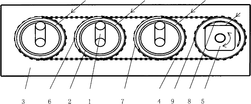
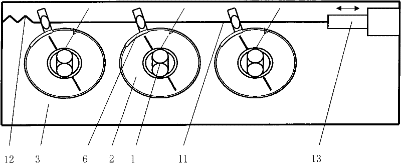
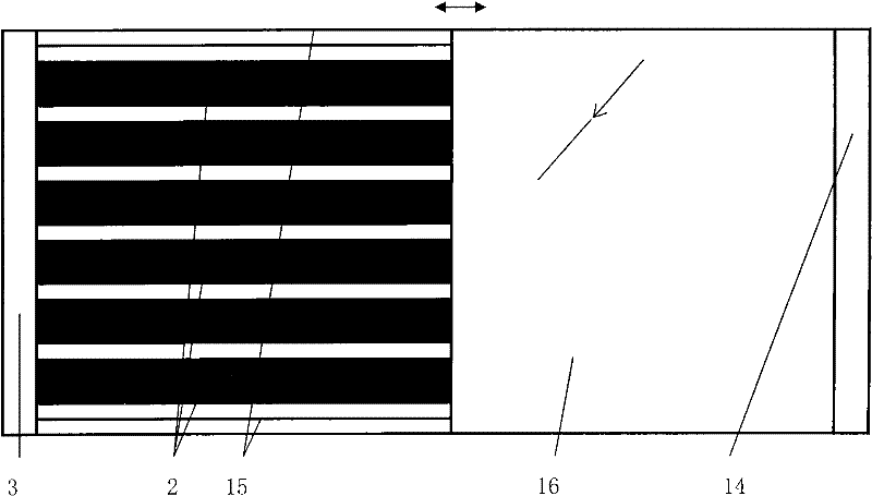
[0020] figure 1 Among them, the vacuum heat collecting element 2 of the internal fin plate metal runner heat exchanger 1, the collection box 3 of the built-in heat exchanger 1 collection pipe, the tail box and the junction box 3 tail box are connected by means of movable cooperation. The connecting parts form a fully automatic metal runner vacuum solar heat collection device with controllable heat collection temperature. Each heat collecting element 2 is connected with a synchronous transmission belt 4 in transmission. The synchronous transmission belt 4 is connected with the motor-driven power head 5 in transmission. The motor-driven power head 5 can be used for forward and reverse rotation. Part of the outer surface of each heat collecting element 2 cover glass tube is coated with black silica gel to form a light-shielding layer 6 . The heat collecting element 2 is connected with the foundation by means of a rotary connection pair. On the cover glass tube that heat colle...


PUM


Abstract

The invention provides a heat collecting temperature controllable manufacturing method of a vacuum solar heat collecting device. Control of heat collecting temperature or empty sunning protection is realized when the heat collecting state of the vacuum solar heat collecting device is changed by shading vacuum heat collecting elements. The heat collecting device manufactured according to the method consists of metal runner vacuum heat collecting elements and a connection box, and is characterized in that: a shading layer is arranged on partial surface of a covering glass tube of each heat collecting element; and a gear or a transmission lug is arranged on the heat collecting lug. Possibly, the heat collecting device consists of vacuum heat collecting elements, a thermal-insulating water tank and fundamental parts, and is characterized in that: a movable shading plate which can rotate with the axes of the heat collecting element is arranged outside each heat collecting element. Otherwise the heat collecting device consists of heat collecting elements and fundamental parts, and is characterized in that: a curtain-shaped object is arranged on a light facing surface of the heat collecting device. The heat collecting device has the advantages that: empty sunning protection can be carried out on the heat collecting device without a heat release facility; and a transmission part and each heat collecting element or the movable shading plate are in transmission connection with a drive mechanism so as to realize automatic control. Three embodiments are provided along with the figures.

Description

technical field [0001] The invention relates to a manufacturing method and a product of a vacuum solar heat collecting device with controllable heat collecting temperature. Background technique [0002] There is a solar heating device not equipped with cooling facilities, which uses a low-heat-sink finned metal runner heat exchanger to exchange heat with an inner glass tube of a vacuum heat collecting tube. In the non-heating season, in addition to hot water supply, because there is no heat dissipation facility and it is inconvenient to cover, the internal temperature is often as high as 230°C or more. 240°C is the degassing temperature of the high borosilicate glass tube, and three-quarters of the released gas is water and oxygen, which have a high probability of reacting with the absorbing film, which will accelerate the aging of the absorbing film. The use of a dedicated cooling tower for heat release requires a large facility fee, site, circulation pump electricity cost...

Claims


Application Information

Patent Timeline
Patent Type & Authority Applications(China)
IPC IPC(8): F24J2/05F24J2/46F24J2/26F24J2/40F24S10/40F24S10/75
CPCF24S40/52Y02E10/40
Inventor 施国樑
Owner HAINING IEMYC SOLAR ENERGY TECH
Why Eureka
Try Eureka