
Hydrolysate self-evaporator

A self-evaporator and hydrolyzate technology, applied in evaporation, chemical instruments and methods, separation methods, etc., can solve the problems of inconvenient repair and maintenance, inconvenient control of liquid level, high cost of repair and maintenance, and reduce maintenance Maintenance cost, easy maintenance and repair, avoiding the effect of airflow impact

Inactive Publication Date: 2011-10-19
SHANDONG WANSHENG ENVIRONMENTAL TECH DEV
View PDF5 Cites 1 Cited by
  • Summary
  • Abstract
  • Description
  • Claims
  • Application Information

AI Technical Summary

Problems solved by technology

The traditional self-evaporator includes a shell, the top of the shell is provided with a secondary steam outlet for discharging secondary steam and non-condensable gas, the bottom of the shell is provided with a hydrolyzate outlet, and the side wall of the shell is provided with The inlet of the hydrolyzate, this kind of self-evaporator cannot realize automatic control in the actual production process, and the control of the liquid level is very inconvenient
[0004] In addition, the traditional self-evaporator of hydrolyzed liquid still has the following disadvantages during use: First, there is an airflow impact when the hydrolyzed liquid enters the shell from the hydrolyzed liquid inlet, and the hydrolyzed liquid and air flow will impact on the shell on the side corresponding to the hydrolyzed liquid inlet. The side wall of the body forms an impact, which affects the service life of the equipment; second, the shell is an integral structure, and its internal repair and maintenance are relatively inconvenient, and the cost of repair and maintenance is relatively high
For the above shortcomings, there is still no good solution

Method used


Image

  • Hydrolysate self-evaporator
  • Hydrolysate self-evaporator

Examples


Embodiment Construction

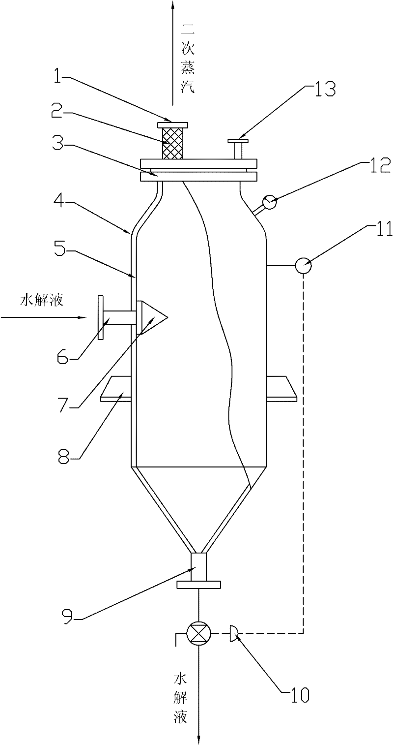
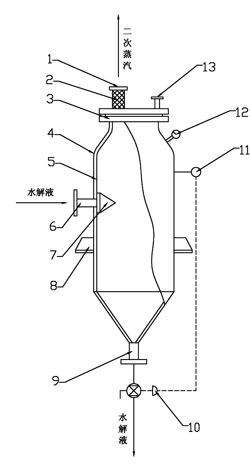
[0018] Such as figure 1 As shown, the hydrolyzed liquid self-evaporator includes a shell 4 and an inner lining 5 arranged in the shell 4. The top of the shell 4 is provided with a secondary steam outlet 1, and the bottom of the shell 4 is provided with a hydrolyzed liquid outlet 6. 4 is provided with a hydrolyzed liquid inlet 6 on the side wall, a liquid level sensor 11 is provided on the side wall of the housing 4, and an electric regulating valve 10 is provided at the hydrolyzed liquid outlet 9. The electric regulating valve 10 and the liquid level The sensor 11 is connected.

[0019] In order to facilitate maintenance and repair, a manhole flange 3 is provided on the top of the casing 4, and a gland is arranged on the upper part of the manhole flange 3, and the secondary steam outlet 1 is provided on the gland.

[0020] A reflux inlet 13 is also provided on the gland.

[0021] In order to prevent the hydrolyzed liquid from entering the casing 4 from impacting the side wall of th...


PUM


Abstract

The invention relates to a hydrolysate self-evaporator, and concretely relates to the hydrolysate self-evaporator which allows automatic control to be realized. The hydrolysate self-evaporator comprises a housing and an inner liner arranged in the housing, the top housing is provided with a secondary steam outlet, the bottom housing is provided with a hydrolysate outlet, and a side wall of the housing is provided with a hydrolysate inlet. The hydrolysate self-evaporator is characterized in that: the side wall of the housing is provided with a liquid level sensor, the hydrolysate outlet is provided with an electric regulating valve, and the electric regulating valve is connected with the liquid level sensor. One side of the hydrolysate inlet which accesses the inner housing is provided with a hydrolysate inlet adapter and a protective plate. In the invention, when the hydrolysate achieves a certain liquid level the, hydrolysate can be automatically discharged through cooperation of the liquid level sensor and the electric regulating valve, and the protective plate has an effect of gas flow compaction prevention, so manpower is saved, the equipment service life is prolonged and the cost of reparation and maintenance can be reduced.

Description

Technical field [0001] The invention relates to a self-evaporator, in particular to a hydrolysis liquid self-evaporator. Background technique [0002] In the percolation process of furfural production, the hydrolysate discharged from the hydrolysis pot contains high heat. In order to recover the heat, the best method at present is to use self-evaporation heat exchange to recover the heat of the hydrolysate. After self-evaporation, the sugar concentration of the hydrolysate can be increased, and harmful substances in the hydrolysate, such as methanol, can be partially removed. After self-evaporation, most of the furfural in the hydrolysate is transferred to the self-evaporating steam, which is very beneficial for the production of furfural from the self-evaporating steam condensate of the hydrolysate. The self-evaporator is an essential equipment in the method of self-evaporation heat exchange and recovery of the heat of the hydrolysate. [0003] In order to control the self-evapo...

Claims


Application Information

Patent Timeline
Patent Type & Authority Applications(China)
IPC IPC(8): B01D1/00
Inventor 柏绪桐王德军陈蓉
Owner SHANDONG WANSHENG ENVIRONMENTAL TECH DEV
Learn More