Method and system for realizing flow intervals among virtual devices
A virtual device and traffic technology, applied in the direction of transmission system, digital transmission system, branch office to provide special services, etc., can solve the problems of high cost of forwarding chip, increase of cost of forwarding chip, unfavorable promotion and application of equipment virtualization technology, etc. To achieve the effect of cost reduction
- Summary
- Abstract
- Description
- Claims
- Application Information
AI Technical Summary
Problems solved by technology
Method used
Image

Examples
Embodiment 1
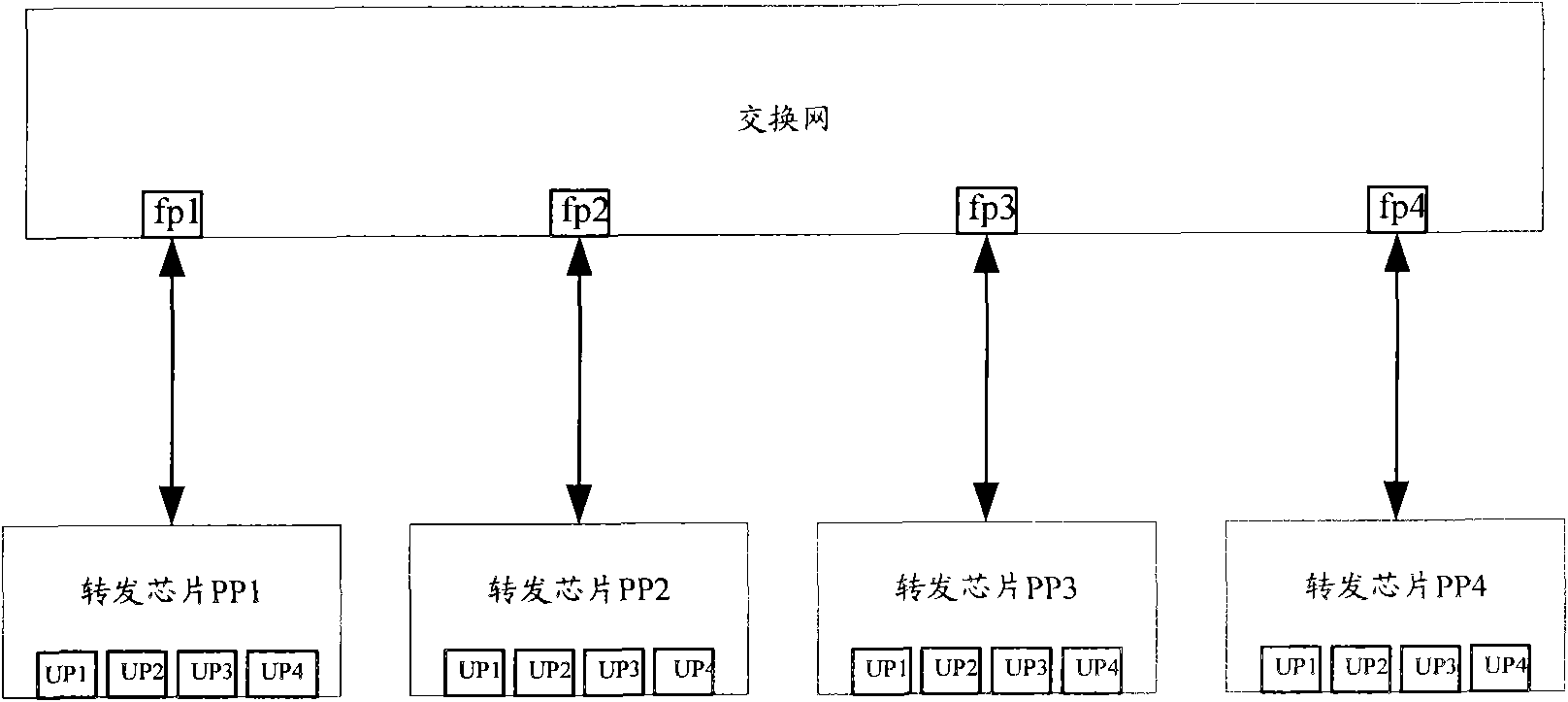
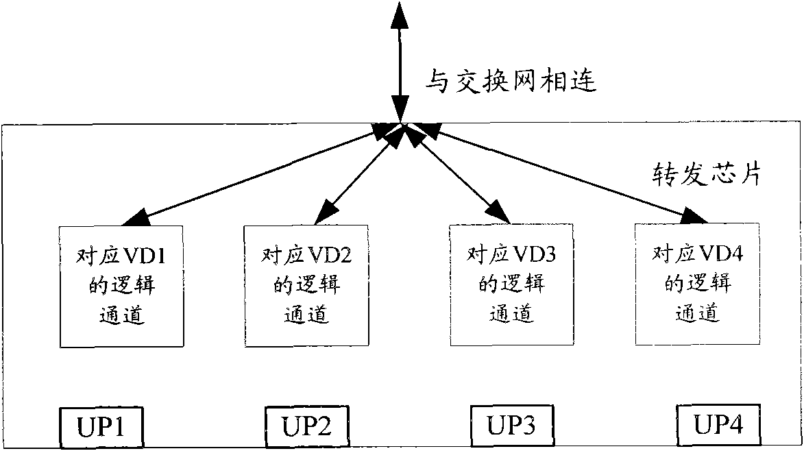
[0058] In this embodiment, it is assumed that the architecture of the distributed switching and routing system is still as figure 1 As shown, the forwarding chip is an ordinary forwarding chip without the virtualization function, and the switching network establishes a logical channel for the VD. In this embodiment, it is also assumed that the forwarding chips include PP1-PP4, and each forwarding chip has four user ports UP1-UP4; the switching network port corresponding to PP1 is fp1, the switching network port corresponding to PP2 is fp2, and the switching network port corresponding to PP3 It is fp3, and the switching network port corresponding to PP4 is fp4.
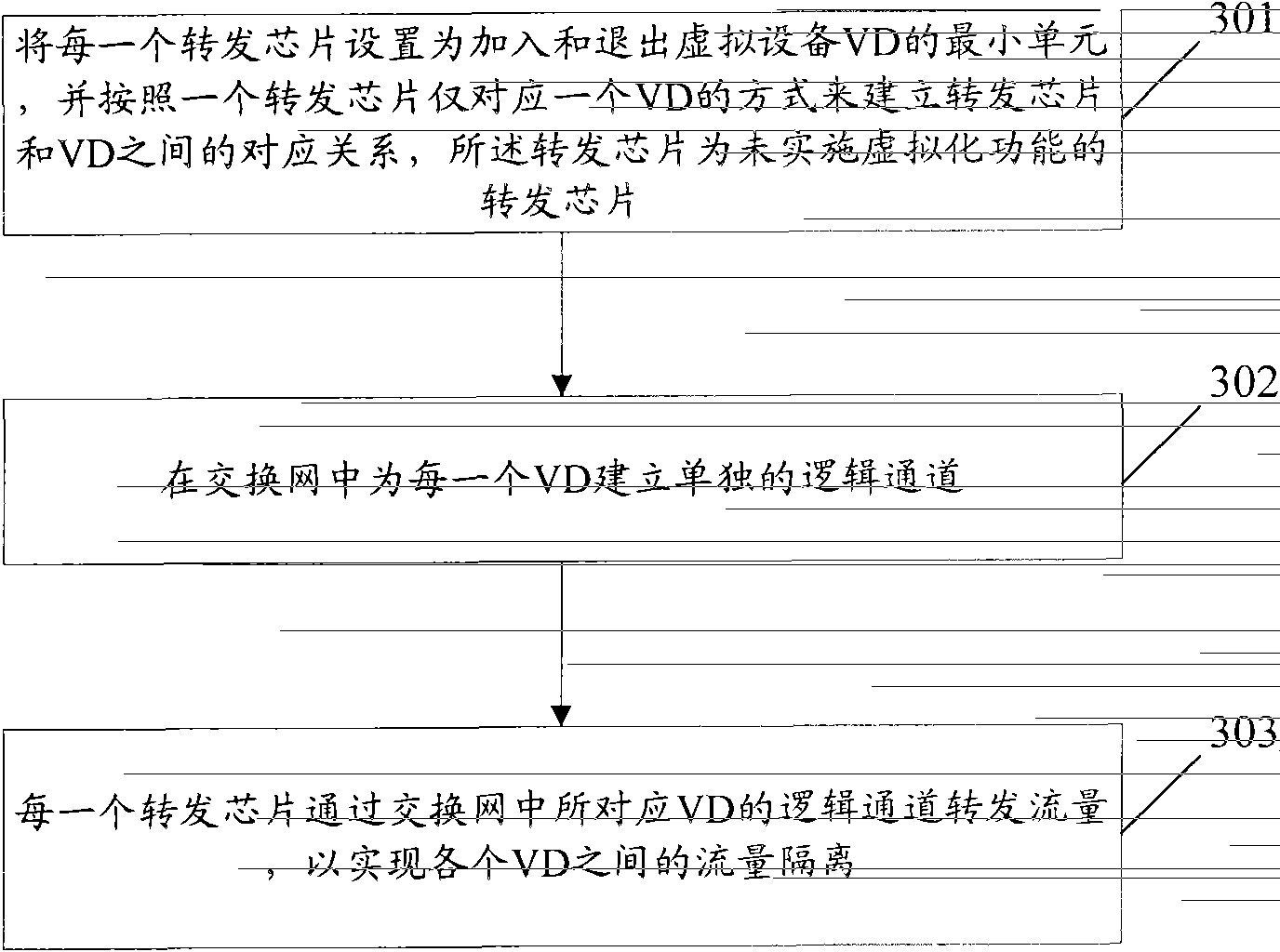
[0059] In this embodiment, it is also assumed that the forwarded traffic is unicast traffic, and the method for realizing traffic isolation is as follows: Figure 4 shown, including:
[0060] Step 401: Set each forwarding chip as the minimum unit for joining and exiting the VD, and establish a corresponding relations...
Embodiment 2
[0072] In this embodiment, it is assumed that the architecture of the distributed switching and routing system is as follows Figure 5As shown, the forwarding chip is an ordinary forwarding chip without the virtualization function, and the switching network establishes a logical channel for the VD. In this embodiment, the forwarding chips include PP1-PP5, and each forwarding chip is subordinate to four user ports UP1-UP4. The switching network port corresponding to PP1 is fp1, the switching network port corresponding to PP2 is fp2, the switching network port corresponding to PP3 is fp3, the switching network port corresponding to PP4 is fp4, and the switching network port corresponding to PP5 is fp5.
[0073] This embodiment also assumes that the forwarded traffic is multicast traffic, and the method for implementing traffic isolation is as follows: Figure 6 shown, including:
[0074] Step 601: Set each forwarding chip as the smallest unit for joining and exiting a VD, and ...
Embodiment 3
[0095] In this embodiment, it is assumed that the architecture of the distributed switching and routing system is still as Figure 5 As shown, the forwarding chip is an ordinary forwarding chip without the virtualization function, and the switching network establishes a logical channel for the VD. In this embodiment, each forwarding chip has four user ports UP1-UP4; the switching network port corresponding to PP1 is fp1, the switching network port corresponding to PP2 is fp2, the switching network port corresponding to PP3 is fp3, and the switching network port corresponding to PP4 is fp3. The network port is fp4, and the switching network port corresponding to PP5 is fp5.
[0096] This embodiment also assumes that the forwarded traffic is broadcast traffic, and the method for implementing traffic isolation is as follows: Figure 7 shown, including:
[0097] Step 701: Set each forwarding chip as the smallest unit for joining and exiting the VD, and establish a corresponding ...
PUM
 Abstract
Description
Claims
Application Information
 - R&D
- Intellectual Property
- Life Sciences
- Materials
- Tech Scout
- Unparalleled Data Quality
- Higher Quality Content
- 60% Fewer Hallucinations
Browse by: Latest US Patents, China's latest patents, Technical Efficacy Thesaurus, Application Domain, Technology Topic, Popular Technical Reports.
© 2025 PatSnap. All rights reserved.Legal|Privacy policy|Modern Slavery Act Transparency Statement|Sitemap|About US| Contact US: help@patsnap.com