


Quick Research
Generate reliable direction feasibility study reports for your R&D in just a few steps.

Technical Q&A
Discover and master advanced knowledge NOW. Basics, ideas, possibilities, all at once.

Find Solutions
As an expert in R&D theories, this can generate solutions to your technical problems instantly.

Evaluate Feasibility
Analyze your overall solution with one click, know your potential R&D risks in advance.

Monitor Landscape
Get weekly tech updates, stay abreast of the latest tech innovations and key insights.
Flat antenna and handheld device
A planar antenna and antenna part technology, applied in the direction of the radiating element structure, etc., can solve problems such as signal interference, and achieve the effect of reducing interference and improving spatial configuration
- Summary
- Abstract
- Description
- Claims
- Application Information
AI Technical Summary
Problems solved by technology
Method used
Image

Examples
Embodiment Construction
[0041] Traditional handheld devices using MIMO have the problems of signal interference and difficult configuration of planar antennas.
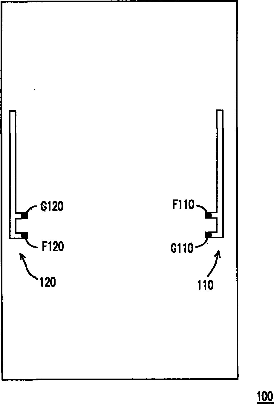
[0042] In contrast, the embodiment of the present invention integrates two planar antennas into one planar antenna, which not only reduces the total headroom of the planar antenna, but also reduces the problem of mutual interference of the planar antennas. Embodiments of the invention will be described in detail below with reference to the accompanying drawings, which illustrate exemplary embodiments of the invention, wherein like reference numerals indicate like or similar elements.
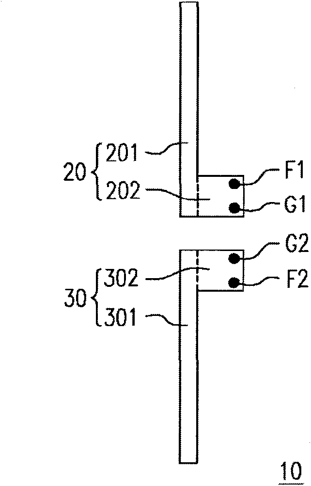
[0043] image 3 is a schematic diagram of two planar antennas according to the first embodiment of the present invention. The antenna part 20 includes a radiation part 201 and an extension part 202 . The extension part 202 extends outward from the radiation part 201 . The extension part 202 has a feeding point F1 and a grounding point G1. The antenna part ...
PUM
 Abstract
Description
Claims
Application Information
 - R&D Engineer
- R&D Manager
- IP Professional
- Industry Leading Data Capabilities
- Powerful AI technology
- Patent DNA Extraction
Browse by: Latest US Patents, China's latest patents, Technical Efficacy Thesaurus, Application Domain, Technology Topic, Popular Technical Reports.
© 2024 PatSnap. All rights reserved.Legal|Privacy policy|Modern Slavery Act Transparency Statement|Sitemap|About US| Contact US: help@patsnap.com