Inspection method for inspecting corrosion under insulation
A technology of corrosion under the insulation layer and inspection method, which is applied in the fields of weather resistance/light resistance/corrosion resistance, material analysis using acoustic wave emission technology, material analysis using sound wave/ultrasonic wave/infrasonic wave, etc., which can solve low efficiency and other problems, and achieve Easy to check the effect
- Summary
- Abstract
- Description
- Claims
- Application Information
AI Technical Summary
Problems solved by technology
Method used
Image
Examples
Embodiment 1
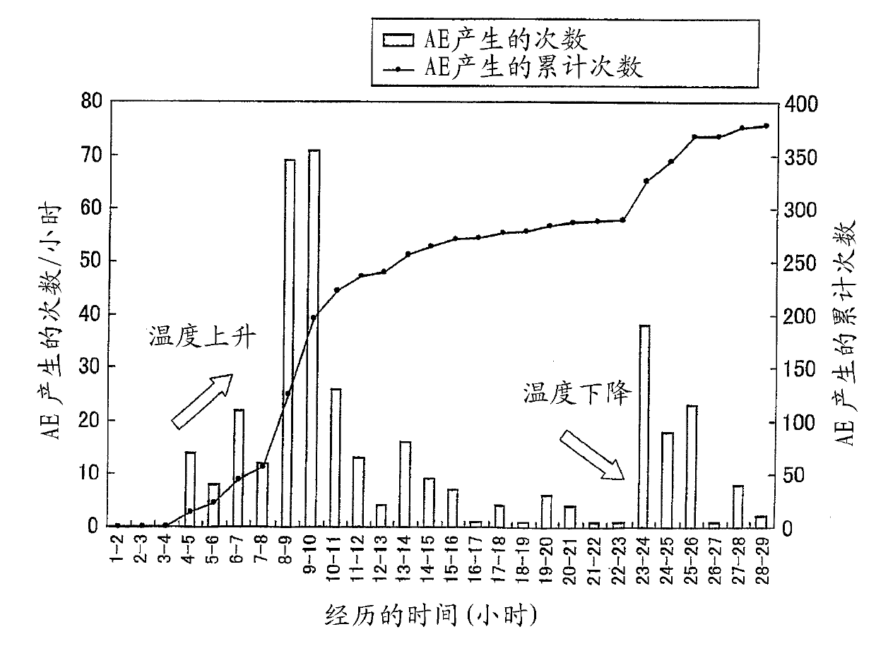
[0084] [Example 1: Evaluation of AE detection in early stages of corrosion]
[0085] (1. Preparation of Solid Model Pipeline)
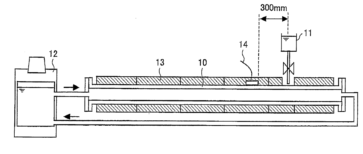
[0086] In order to evaluate the CUI detection method using FOD sensor, first prepared as Figure 4 The solid model pipeline shown in .
[0087] A heat insulating material 13 was attached to a pipe 10 made of carbon steel having a length of 5 m. The silicone oil heated by the heating device 12 circulates through the tube 10 . Corrosion is artificially accelerated in order to effectively cause CUI. More specifically, corrosion occurs as described below. Pure water is continuously dripped onto the surface of the pipe 10 from the dripping device 11, and the amount of addition is finely adjusted to repeatedly produce a wet state and a dry state on the pipe 10 (that is, to produce the so-called " nuregawaki" status). In addition to this water dripping, common salt is applied to the surface of the tube 10 . Furthermore, in order to accelerate corrosio...
Embodiment 2
[0093] [Example 2: Evaluation of AE detectable distance]
[0094] (1. Preparation of Solid Model Pipeline)
[0095] In the solid model pipe prepared in the same manner as in Example 1, corrosion was artificially produced and accelerated in the same manner as in Example 1.
[0096] (2. Evaluation of AE detection)
[0097] AE detection was evaluated in the same manner as in Example 1, with the following exceptions: about 3 months after the onset of artificially accelerated corrosion, the evaluation was carried out on a solid model pipeline in an intermediate stage of corrosion, and by using U-bolts The FOD sensor was firmly connected to the pipe portions of the solid model piping 2000 mm, 3000 mm, and 3900 mm away from the corroded portion (where the pure water was dropped), respectively. Here, it was evaluated whether and how effectively AE detection could be performed using the FOD sensor so far from the corroded portion.
[0098] Image 6 The AE detection results of the F...
Embodiment 3
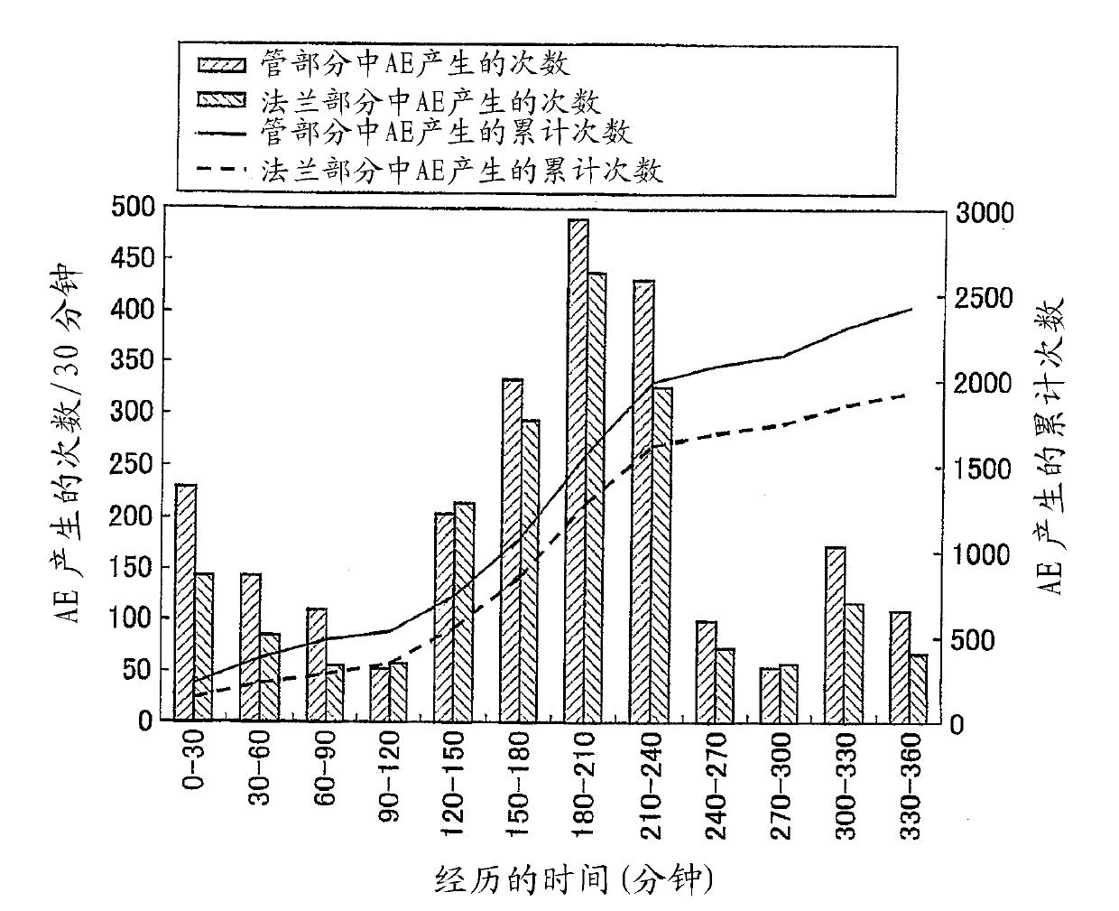
[0100] [Example 3: Comparison between pipe section and flange section for AE detection]
[0101] (1. Preparation of Solid Model Pipeline)
[0102] In the solid model pipe prepared in the same manner as in Example 1, corrosion was artificially created and accelerated in the same manner as in Example 1.
[0103] (2. Evaluation of AE detection)
[0104] AE detection was evaluated in the same manner as in Example 1, with the following exceptions: about 5 months after the onset of artificially accelerated corrosion, the evaluation was performed on a mock-up pipeline in a later stage of corrosion, and the FOD sensor They are respectively connected to the pipe part 3900mm away from the corroded part (where pure water is added) and the flange part 3950mm away from the corroded part. The AE detection results at the pipe portion are compared with the AE detection results at the flange portion. The FOD sensor connected to the pipe part is firmly connected thereto using U-bolts, and th...
PUM
| Property | Measurement | Unit |
|---|---|---|
| wavelength | aaaaa | aaaaa |
Abstract
Description
Claims
Application Information
 - R&D
- Intellectual Property
- Life Sciences
- Materials
- Tech Scout
- Unparalleled Data Quality
- Higher Quality Content
- 60% Fewer Hallucinations
Browse by: Latest US Patents, China's latest patents, Technical Efficacy Thesaurus, Application Domain, Technology Topic, Popular Technical Reports.
© 2025 PatSnap. All rights reserved.Legal|Privacy policy|Modern Slavery Act Transparency Statement|Sitemap|About US| Contact US: help@patsnap.com


