Method for analyzing dynamics of aviation multi-rotor coupling system

A technology of coupling system and analysis method, which is applied in the test of engine, test of machine/structural components, test of machine gear/transmission mechanism, etc., can solve the problems of time-consuming calculation and difficult analysis, and achieve improved accuracy and simple expression. , the effect of accurate description

Inactive Publication Date: 2011-09-28
NORTHWESTERN POLYTECHNICAL UNIV
View PDF0 Cites 11 Cited by
  • Summary
  • Abstract
  • Description
  • Claims
  • Application Information

AI Technical Summary

Problems solved by technology

[0004] In order to overcome the deficiencies in the existing dynamics analysis methods of aeronautical multi-rotor coupling systems, such as analysis difficulties and time-consuming calculations when considering the supporting system and other rotor surrounding structures, the present invention provides a new dynamic analysis method for aeronautical multi-rotor coupling systems Analytical method

Method used


Image

  • Method for analyzing dynamics of aviation multi-rotor coupling system
  • Method for analyzing dynamics of aviation multi-rotor coupling system
  • Method for analyzing dynamics of aviation multi-rotor coupling system

Examples


Embodiment Construction

[0042] Now in conjunction with accompanying drawing and embodiment this invention is described further, the analysis method of aviation multi-rotor coupling system dynamics comprises the steps:

[0043] Step 1: Establish a dynamic model of the aeronautical multi-rotor coupling system;

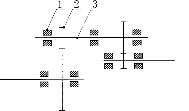
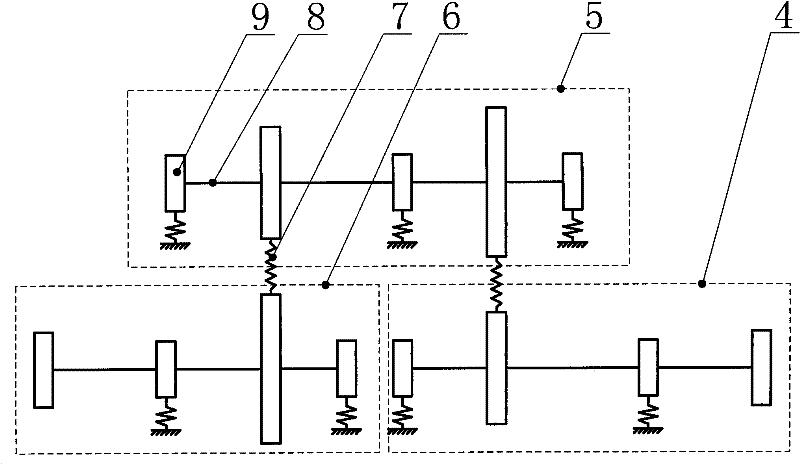
[0044] figure 1 , is the motion diagram of the aeronautical multi-rotor coupling system. The aeronautical multi-rotor coupling system includes 4 gears 2, 7 bearings 1, and 3 shafts 3. The geometric parameters, materials, and working conditions of the aeronautical multi-rotor coupling system are all known. ; Firstly, the aviation multi-rotor coupling system is separated to form three units at the coupling part, and the coupling part here is gear 2; the lumped parameter method is used to discretize each unit, see figure 2 , the discretized first unit 4 includes two equivalent springs 7 of bearings 1 and four nodes 9 connected by three massless elastic shaft segments 8, the second unit 5 include...


PUM


Abstract

The invention discloses a method for analyzing dynamics of an aviation multi-rotor coupling system, and belongs to the field of rotor dynamics. By means of an idea of finite element method to solve problems, the method comprises the following steps: separating the aviation multi-rotor coupling system at coupling parts to form independent rotors; taking each rotor as a unit, and taking the coupling force of each coupling part as an external force of the unit of the coupling part to obtain a dynamic differential equation of each unit; analyzing the coupling force of each coupling part ob acquire a coupling matrix and an equation of the coupling force; and leading the dynamic differential equation of each unit and the equation of the coupling force of each unit to be simultaneous to obtain a dynamic differential equation of the aviation multi-rotor coupling system, and solving to acquire the dynamic characteristics of the aviation multi-rotor coupling system. The method is clear in thread, simple and standard in expression, and suitable for analysis on dynamics of the aviation multi-rotor coupling system, can accurately describe the coupling parts, and improves the accuracy of calculation results.

Description

technical field [0001] The invention relates to the field of rotor dynamics, in particular to an analysis method for the dynamics of an aviation multi-rotor coupling system. Background technique [0002] Aeroengines have a decisive impact on the performance of aircraft and the success or failure and progress of aircraft development, and are of great significance to national defense and national economy. Aeroengine is a highly knowledge-intensive high-tech equipment, and there are many scientific problems that need to be solved. Among them, the vibration of aeroengine has always been the focus of attention. There are many reasons for the excessive vibration of the aero-engine, and the most basic reason is that the structural design of the aero-engine accessory transmission system is unreasonable. The aero-engine accessory drive system is a typical aero-engine multi-rotor coupling system, which not only provides power for the fuel pump, lubricating oil pump and generator of t...

Claims


Application Information

Patent Timeline
Patent Type & Authority Applications(China)
IPC IPC(8): G06F19/00G01M13/02G01M15/00
Inventor 王三民杜佳佳王颖刘海霞相涯范业森
Owner NORTHWESTERN POLYTECHNICAL UNIV
Why Eureka
Try Eureka