
Connector removing jig and connector removing method using the same

A technology for connectors and unclamping, which is applied to the parts of the connecting device, the connection/disconnection of the connecting device, and the connection, etc., which can solve problems such as difficult operation

Inactive Publication Date: 2011-09-21
FUJITSU LTD
View PDF1 Cites 3 Cited by
  • Summary
  • Abstract
  • Description
  • Claims
  • Application Information

AI Technical Summary

Problems solved by technology

When connectors equipped with such a locking mechanism are arranged in high density, it becomes more difficult to unplug the cable-side connector from the board-side connector

Method used


Image

  • Connector removing jig and connector removing method using the same
  • Connector removing jig and connector removing method using the same
  • Connector removing jig and connector removing method using the same

Examples


Embodiment

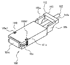
[0029] First, for ease of understanding Figure 7 The pull-off jig 1 of the present embodiment described in, refer to Figure 1 to Figure 5 The cable-side connector 100 that can be detached by the detachment jig 1 will be described.

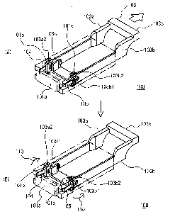
[0030] figure 1 It is a perspective view of the board-side connector 50 and the cable-side connector 100 . figure 2 for following with figure 1 A perspective view of the cable-side connector 100 viewed from a different side. image 3 It is a perspective view of the inside of the cable-side connector 100 . image 3 (A) is a figure which shows the state which the 1st engaging claw 104 and the 2nd engaging claw 105 are closed, image 3 (B) is a figure which shows the state which the 1st engaging claw 104 and the 2nd engaging claw 105 opened. Figure 4 for following with image 3 A perspective view of the interior of the cable-side connector 100 viewed from a different side. Figure 4 (A) is a figure which shows the state which the 1st engag...


PUM


Abstract

A connector removing jig (1) allowing a cable-side connector to be easily removed from a substrate-side connector even when a number of cables are closely spaced. The removing jig (1) comprises a frame member (30) and an arm member (10). The arm member (10) comprises a first side plate (11) on which a first shaft hole (11a) is provided, and a second side plate (12) on which a second shaft hole (12a) is provided, the second side plate (12) being disposed opposite to the first side plate (11). The arm member (10) further comprises, on its forefront side, an engaging portion (13) which is engaged with a lever portion (103) of a cable-side connector (100). The frame member (30) has, on its forefront side, an abutting portion (31) to be abutted against a back surface of a connector body (101) of the cable-side connector (100). The frame member (30) further comprises a first guiding trench (32a) which corresponds to the first shaft hole (11a), a second guiding trench (33a) which corresponds to the second shaft hole (12a), and a first window (35) from which the engaging portion (13) moves in and out.

Description

technical field [0001] The invention relates to a jig for pulling out a connector and a method for pulling out a connector using the jig. Background technique [0002] In recent years, there are electronic devices in which a plurality of connectors for connecting cables are arranged at high density in vertical and horizontal directions. This tendency becomes more remarkable against the background of promotion of miniaturization of electronic equipment. When a plurality of connectors are arranged at a high density, cables are densely packed, and it is difficult to secure an operation area required for unplugging the connectors. That is, if a plurality of cables are arranged at a high density in the vertical direction and the left-right direction so that the cables are densely packed, when a specific cable is pulled out, the connector to be pulled out cannot be reached by hand due to the influence of other densely packed cables. Therefore, in order to remove a specific cable...

Claims


Application Information

Patent Timeline
IPC IPC(8): H01R43/26H01R13/639
CPCH01R13/6275H01R13/6335H01R43/26Y10T29/49117Y10T29/49147Y10T29/49204Y10T29/53209Y10T29/53283H01R13/639
Inventor 平野正芳真壁英二今本孝志佐藤宏
Owner FUJITSU LTD
Learn More