Eureka AIR delivers breakthrough ideas for toughest innovation challenges, trusted by R&D personnel around the world.

Power converter

A technology of a power conversion device and a three-level inverter is applied in the direction of output power conversion devices, electrical components, conversion equipment for intermediate conversion to DC conversion, etc., to achieve the effect of simplifying the insulation structure

Active Publication Date: 2011-09-21
FUJI ELECTRIC CO LTD
View PDF3 Cites 3 Cited by
  • Summary
  • Abstract
  • Description
  • Claims
  • Application Information

AI Technical Summary

Problems solved by technology

[0008] But when Figure 11 and Figure 12 In the example shown in the prior art, the primary winding of the transformer 120 is connected to the AC power source 119, and the first AC input terminal 101 and the second AC input terminal 104 of the single-phase three-level inverter units S1 and S2 are respectively It is connected to the secondary windings 121, 122 and 123, 124 of the transformer 120. Therefore, when the voltage between the terminals of the smoothing capacitors 103 and 106 is Edc, the operation of the single-phase three-level inverter units S1 and S2 mode, the voltage applied between adjacent secondary windings sometimes reaches a high voltage of 4Edc, and there are unsolved problems as follows: It is necessary to ensure insulation corresponding to the highest voltage between secondary windings, and the size of the transformer is increased.

Method used


Image

  • Power converter
  • Power converter
  • Power converter

Examples


Embodiment Construction

[0079] Embodiments of the present invention will be described below with reference to the drawings. Here, a single-phase output circuit will be described as an example.

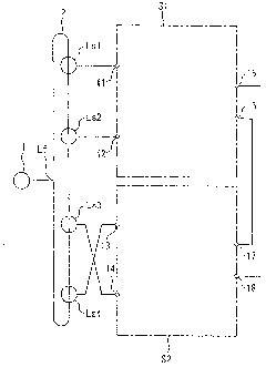
[0080] figure 1 is a block diagram showing the power conversion device according to the first embodiment of the present invention. In the figure, 1 denotes an AC power supply, and the AC power output from the AC power supply 1 is input to the primary winding Lf of the transformer 2 . Four secondary windings Ls1 to Ls4 are provided on the secondary side of the transformer 2 . Also, the first single-phase three-level inverter unit S1 is connected to the secondary windings Ls1 and Ls2, and the second single-phase three-level inverter unit S2 is connected to the secondary windings Ls3 and Ls4.

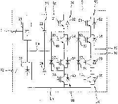
[0081] The single-phase three-level inverter unit S1 includes a first AC input terminal 11 , a second AC input terminal 12 , a first AC output terminal 15 , and a second AC output terminal 16 . In addition, the singl...


PUM


Abstract

The present invention provides a power converter. The task of the invention is to restrain application of a high voltage between adjacent secondary windings of a transformer which is connected with a plurality of single-phase three-level inverter units thereby simplifying an insulation structure and minimizing the transformer. A settlement solution of the invention is characterized in that: when at least first AC input terminals (11-14) of a first single-phase three-level inverter unit (S1) and a second single-phase three-level inverter unit (S2) are connected with secondary windings (Ls1-Ls4) of the transformer (2), a first AC input terminal and a second AC input terminal are connected with opposed secondary windings for each single-phase three-level inverter unit; and for the other single-phase three-level inverter unit, the first AC input terminal and the second AC input terminal are connected with secondary windings which are crossed, thereby restricting application of the high voltage between the adjacent secondary windings.

Description

technical field [0001] The present invention relates to a power conversion device having a structure in which single-phase three-level inverters (inverters) are connected in series. Background technique [0002] As such a power conversion device, for example, a high-voltage inverter device is known in which single-phase inverter units U1 to U6, V1 to V6, W1 to W6 having a forward conversion part and a reverse conversion part Connect a plurality of them in series, input AC power to the forward conversion part of each single-phase inverter unit through two input transformers, and store it in the panel. In this high-voltage inverter device, the Each single-phase inverter unit is supported in such a way that the insulation support frame can be freely drawn out while maintaining the insulation distance, and the wiring leading from the two input transformers to each single-phase inverter unit and each single-phase inverter are fixed through the front support in the panel. The wir...

Claims


Application Information

Patent Timeline
IPC IPC(8): H02M5/44H02M7/483H02M7/5387
Inventor 花泽昌彦河野正志
Owner FUJI ELECTRIC CO LTD
Why Eureka
Eureka Blog
Learn More