Eureka AIR delivers breakthrough ideas for toughest innovation challenges, trusted by R&D personnel around the world.

Pneumatic full-automatic pocket patching machine

The technology of a pneumatic bag sticking machine is applied in the direction of cloth feeding mechanism, sewing machine components, sewing machine control devices, etc., which can solve the problems of rising manufacturing cost and limited promotion, and achieve low manufacturing cost, high transmission accuracy and convenient operation. Effect

Inactive Publication Date: 2011-09-21
SHANGHAI GUIYI SEWING EQUIP MFG
View PDF3 Cites 44 Cited by
  • Summary
  • Abstract
  • Description
  • Claims
  • Application Information

AI Technical Summary

Problems solved by technology

In addition, in recent years, some foreign advanced sewing equipment manufacturers such as Japan, Italy and other countries have developed an automatic bagging machine with non-iron folding technology, which has a high degree of automation and can realize non-ironing, folding A series of automatic procedures such as edge, feeding, sewing and blanking. This type of machine generally adopts a high-precision transmission method, such as a motor-driven screw, a turbine, and other transmission methods similar to CNC machine tools. Improve the transmission accuracy of each link in the automation process, so that the manufacturing cost of this fully automatic bagging machine has risen sharply, and the price of each machine is as high as 300,000 to 600,000 yuan, making it difficult for most clothing manufacturers to accept this expensive price. This limits the spread of such technologies

Method used

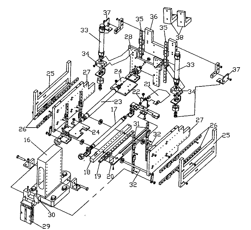
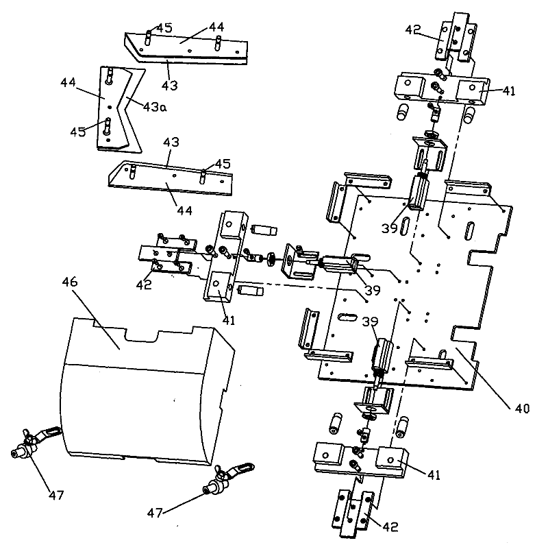

Image

  • Pneumatic full-automatic pocket patching machine
  • Pneumatic full-automatic pocket patching machine
  • Pneumatic full-automatic pocket patching machine

Examples


Embodiment Construction

[0018] A preferred embodiment will be given below, and the present invention will be described more clearly and completely in conjunction with the accompanying drawings.

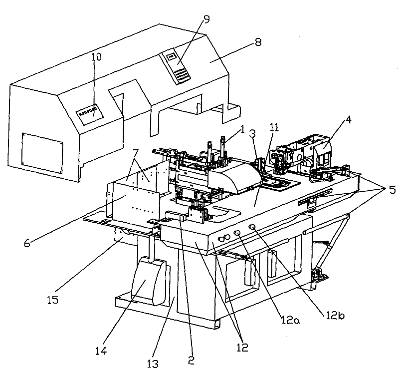
[0019] like figure 1 As shown, the pneumatic fully automatic bagging machine of the present invention includes a frame steel plate, a pneumatic automatic iron-free folding mechanism 1, a pneumatic automatic feeding mechanism 2, a coordinate pattern transmission mechanism 3, and a rotary shuttle pattern machine sewing head 4 , Pneumatic automatic feeding mechanism 5, air pressure adjustment mounting plate 6, solenoid valve mounting plate 7, protective cover 8, control display plate 9, quick change mechanism control plate 10, stainless steel work table 11, stainless steel enclosure 12, frame 13 , vacuum cleaner 14 and electrical control box 15, the pneumatic automatic non-ironing hemming mechanism 1 is arranged on the top of the back of the frame steel plate, and the pneumatic automatic feeding mechanism 2 is ...


PUM


Abstract

The invention discloses a pneumatic full-automatic pocket patching machine. The machine comprises a rack steel plate, a pneumatic automatic non-ironing and folding mechanism and the like, wherein the pneumatic automatic non-ironing and folding mechanism is arranged above the rear part of the rack steel plate; a pneumatic automatic feeding mechanism is transversely arranged in front of the pneumatic automatic non-ironing and folding mechanism; a coordinate pattern transmission mechanism is arranged on the left of the pneumatic automatic non-ironing and folding mechanism; a rotating shuttle type pattern sewing machine sewing head is arranged in front of the rack steel plate on the right and is transversely arranged; an air pressure adjusting mounting plate is arranged at the left rear end of the rack steel plate; solenoid valve mounting plates are arranged on the right of the air pressure adjusting mounting plate; a shield is arranged on the rear half part of the whole rack steel plate; stainless steel coamings are arranged below a stainless steel working table; a first starting switch and a second starting switch are arranged above one stainless steel coaming; a dust collector is arranged on the left of a rack; and an electrical appliance control box is arranged behind the rack and on the lower part of the rack steel plate. The machine has the effects of lowering the manufacturing cost and realizing automatic programs such as non-ironing programs and the like.

Description

technical field [0001] The invention relates to the technical field of sewing equipment, in particular to a pneumatic automatic bag sticking machine. Background technique [0002] There are many types of pocket patching machines, and the general automation program of pocket patching machines is very low. Most of them are single-type pocket patching machines that are reformed from pattern machine sewing machines and can only realize sewing. At present, the semi-automatic bagging machine used in the garment industry in this field occupies a certain market. This bagging machine includes automatic procedures such as feeding, sewing and blanking, and must be equipped with an electric heating steam machine before sewing the bagging. Folding machine, after the bag is folded and flattened, then the bagging process is performed, so it is called a semi-automatic bagging machine. In foreign countries, such as the semi-automatic bagging machine of Pfaff in Germany and the introduction o...

Claims


Application Information

Patent Timeline
IPC IPC(8): D05B21/00D05B33/00D05B35/04D05B35/06D05B69/08
Inventor 黄志云
Owner SHANGHAI GUIYI SEWING EQUIP MFG
Why Eureka
Eureka Blog
Learn More