


Quick Research
Generate reliable direction feasibility study reports for your R&D in just a few steps.

Technical Q&A
Discover and master advanced knowledge NOW. Basics, ideas, possibilities, all at once.

Find Solutions
As an expert in R&D theories, this can generate solutions to your technical problems instantly.

Evaluate Feasibility
Analyze your overall solution with one click, know your potential R&D risks in advance.

Monitor Landscape
Get weekly tech updates, stay abreast of the latest tech innovations and key insights.
Method and apparatus for automatic assigning of devices
A distribution method and equipment technology, applied in the direction of measuring devices, utilization of re-radiation, instruments, etc., can solve the problems of distribution accuracy impact, distribution error probability increase, error dispersion, etc., to increase the distribution success rate and increase the distribution success rate , Improve the effect of distribution accuracy
- Summary
- Abstract
- Description
- Claims
- Application Information
AI Technical Summary
Problems solved by technology
Method used
Image

Examples
no. 1 example
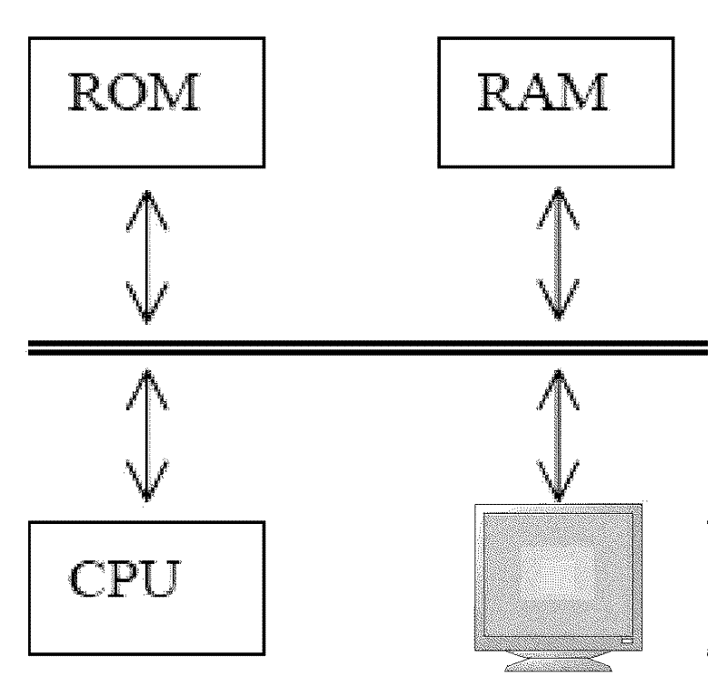
[0026] figure 1 A wireless network-based lighting area is schematically illustrated, where a topology map of this lighting area is shown, that is, the positions (1,1), (1,2), ... ( 4,4) are all known. At nodes in the lighting area lighting devices 1, 2, ..., 16 are installed, but which lighting device corresponds to which node is unknown. Such as figure 2As shown, each node includes a lighting element 210 , a wireless communication module 220 (such as a ZigBee RF module), and a power supply 230 . The wireless communication module 220 may perform wireless communication with wireless communication modules of other nodes based on the ZigBee RF protocol or other protocols, and establish the wireless network 100 . The signal sent by any device carries the unique identification information of the sending device; the receiving device can determine the sending device of the radio signal based on the identification information, and measure the measured distance-related information ...
no. 2 example
[0056] Before describing an embodiment according to another aspect of the present invention, relevant knowledge about allocated safety margins will first be introduced. Such as Figure 6 As shown, in the topological graph in which nodes are distributed in a square grid shape, reference devices 1 and 2 are located at reference nodes (1, 1) and (1, 2) respectively; other unknown target lighting devices are located at other nodes , the configuration of the wireless communication module of each lighting device is the same (for example, the antenna gain and transmit power are the same). When the assigned node (2, 1) closest to node (1, 1) is assigned, because the distance between node (2, 1) and node (1, 1) is the distance between node (1, 1) and all nodes ( The smallest one of the distances between each of the reference nodes (1, 2) except the reference node (1, 2), the assignment can be based on the following principle: Among all target devices, the illumination with the largest...
no. 3 example
[0091] The allocation success rate of the entire topology map is related to the number of nodes in the topology map. Such as Figure 10 As shown, the simulation results illustrate the relationship between the number of successful allocation operations and the number of nodes in the topology map; its ordinate indicates how many of the 50 allocation operations are successful, and the abscissa indicates the standard deviation of the measurement error of RSSI ( It is assumed that the RSSI measurement error is Gaussian distributed with zero mean). The allocation method employed by this simulation is the method used in the first embodiment described above. As can be seen, as the number of nodes increases from 16 to 25 (each including three reference nodes), the number of successful allocation operations decreases. The reason is: the more nodes there are, the more likely misassignments to multiple nodes will occur overall. At the same time, a wrongly assigned node can be used as a...
PUM
 Abstract
Description
Claims
Application Information
 - R&D Engineer
- R&D Manager
- IP Professional
- Industry Leading Data Capabilities
- Powerful AI technology
- Patent DNA Extraction
Browse by: Latest US Patents, China's latest patents, Technical Efficacy Thesaurus, Application Domain, Technology Topic, Popular Technical Reports.
© 2024 PatSnap. All rights reserved.Legal|Privacy policy|Modern Slavery Act Transparency Statement|Sitemap|About US| Contact US: help@patsnap.com