
Light emitting diode (LED) lamp with front and rear cavity structures

A technology of LED lamps and LED lamp beads, which is applied in parts of lighting devices, semiconductor devices of light-emitting elements, cooling/heating devices of lighting devices, etc. Problems such as weak connection and increased heat dissipation efficiency of the heat sink can prevent rain and snow from penetrating into the interior of the lamp, prevent the lamp from being easily damaged, and have a good heat dissipation effect

Inactive Publication Date: 2013-08-14
宁波亿鑫诚电器有限公司
View PDF4 Cites 0 Cited by
  • Summary
  • Abstract
  • Description
  • Claims
  • Application Information

AI Technical Summary

Problems solved by technology

[0004] The purpose of the present invention is to solve the above-mentioned prior art, because the flatness of the lamp housing is too low, the heat-conducting silicone grease is used, it is easy to dry and crack, and the LED aluminum substrate and the power supply are superimposed, resulting in ineffective convection and heat dissipation, often raining The snow seeped into the interior of the lamp, causing the lamp to be vulnerable. The connection angle between the LED lamp and the connecting rod is inconvenient to adjust, and the ideal lighting effect cannot be achieved. The connection of the power supply line is not firm and it is not easy to connect. The LED lamp with cavity structure can disperse the heat source, produce effective convection heat dissipation, shorten the distance of heat conduction, and increase the heat dissipation efficiency of the heat sink; it can effectively prevent rain and snow from penetrating into the lamp, and avoid the lamp from being easily damaged; the connection angle is convenient It can be adjusted to achieve the best lighting effect; it can ensure that the power supply line, regardless of the thickness, can be firmly connected without frequent maintenance

Method used

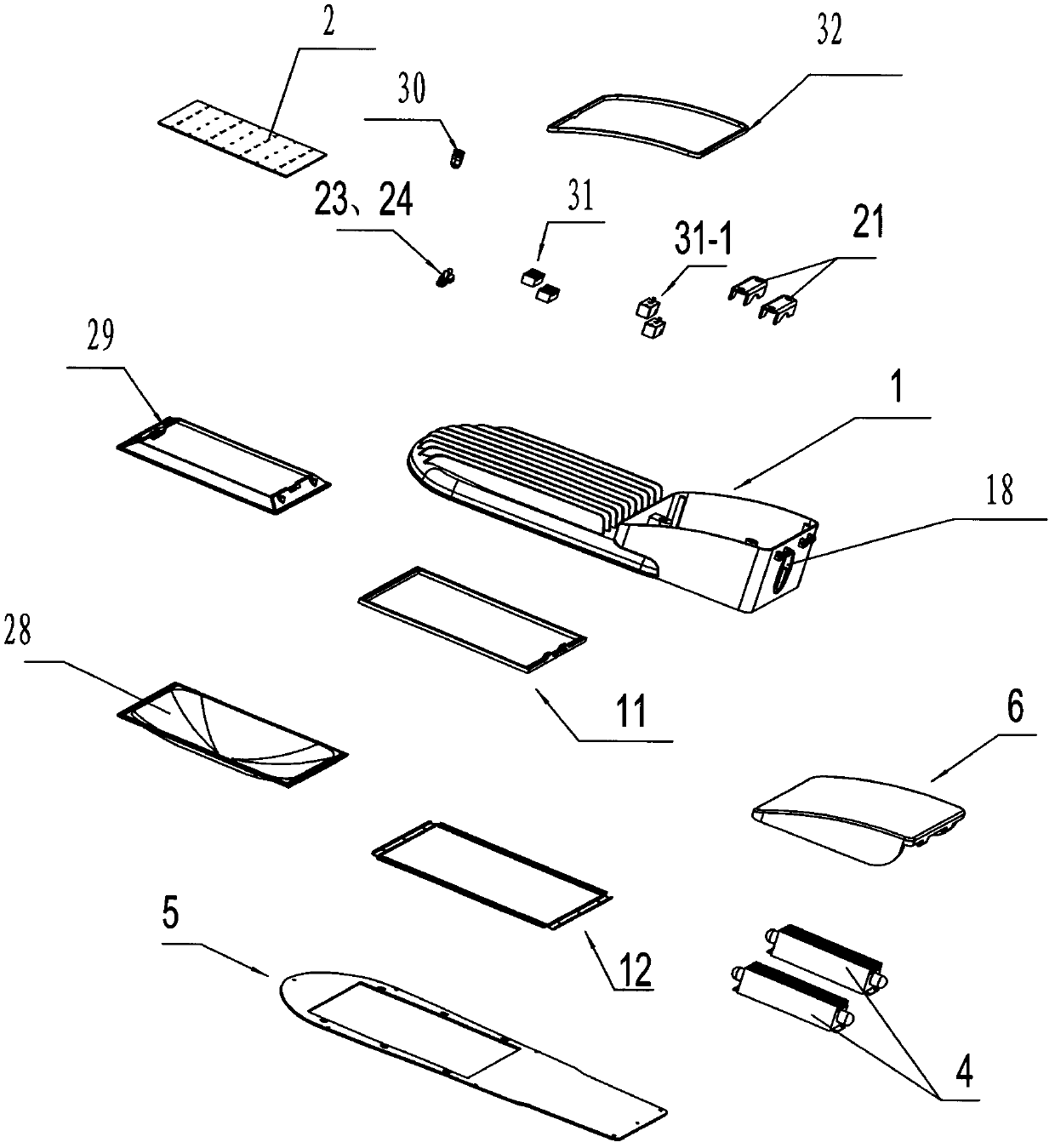

Image

  • Light emitting diode (LED) lamp with front and rear cavity structures
  • Light emitting diode (LED) lamp with front and rear cavity structures
  • Light emitting diode (LED) lamp with front and rear cavity structures

Examples


Embodiment 1

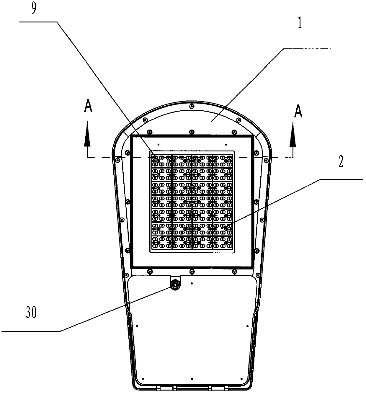
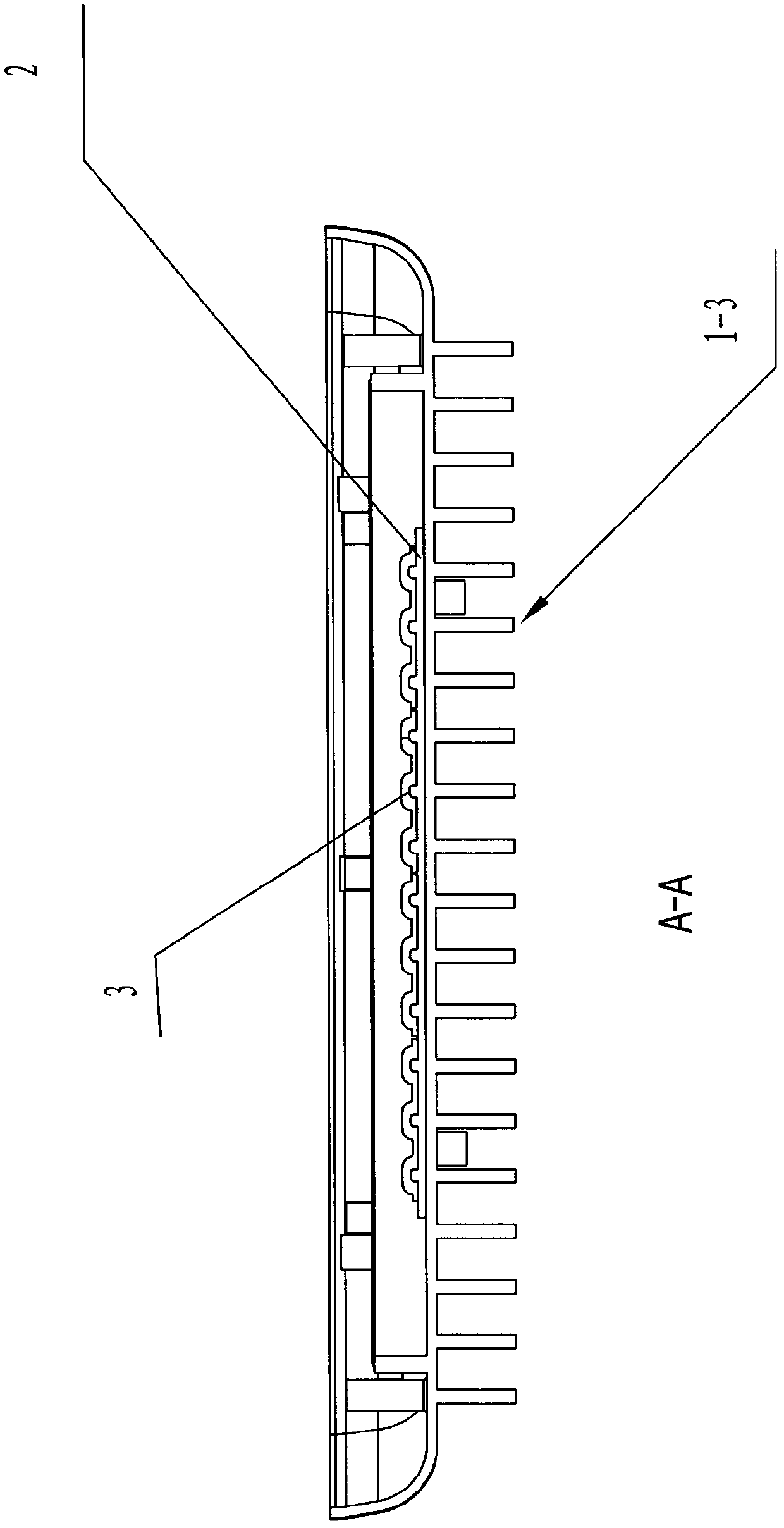
[0047] Such as Figure 1 to Figure 4 As shown, an LED lamp with a front and rear cavity structure includes a lamp base housing 1, an LED aluminum substrate 2, several LED lamp beads 3 and a power supply 4. The lamp base housing 1 includes a housing main body 1-1 and The heat sink 1-2, the heat sink 1-2 is composed of several longitudinally evenly distributed heat dissipation ribs 1-3, the LED lamp beads 3 are installed on the front of the LED aluminum substrate 2, and are evenly distributed, and the one has The LED lamp with the front and rear chamber structure also includes a bottom cover 5 and a rear cover 6. The lamp housing 1 includes a front part and a rear part, and the bottom cover 6 includes an upper part and a lower part. The front part of the lamp housing 1 and the bottom cover The upper part of 5 forms the front chamber 7, the rear part of the lamp housing 1 and the rear cover 6 form the rear chamber 8, the LED aluminum substrate 2 and several LED lamp beads 3 are a...

Embodiment 2-5

[0053] In Embodiment 2-5, the elevation angle α of the LED street lamp composed of the above-mentioned drawings and the installation direction of the cylindrical light pole 16 and the direction of the bottom cover 5 is shown in the following figure:

[0054]

[0055] The method of adjusting the elevation angle of LED street lamps: In Embodiments 2, 3, 4, and 5, first loosen the light pole pressure plate screw 22, and then support the upper end of the cylindrical light pole 16 on the adjustment step b of the adjustment baffle 20 , c, d, e, and then pass the light pole pressure plate screw 22 through the light pole pressure plate 21, screw it into the pressure plate screw hole 19-1, and tighten it, the cylindrical light pole 16 is closely connected with the main body 1-1 of the lamp housing up.

[0056] The rest are the same as embodiment 1.


PUM


Abstract

The invention discloses a light emitting diode (LED) lamp with front and rear cavity structures, and belongs to the technical field of lighting devices. The LED lamp comprises a lamp cap shell, a bottom cover and a rear cover, wherein the front part of the lamp cap shell and the upper part of the bottom cover form a front cavity; the rear part of the lamp cap shell and the rear cover form a rear cavity; an LED aluminum substrate and a plurality of LED lamp beads are arranged in the front cavity; a power supply is arranged in the rear cavity; the back surface of the LED aluminum substrate is directly attached to the inner surface of a shell main body; a cooling fin is arranged outside the front part of the lamp cap shell; the LED lamp beads are longitudinally arranged to form a plurality of straight bodies and are aligned with straight cooling ribs of the cooling fin; a water-proof structure which consists of a seal ring, a pressing strip and a pressing strip screw is also arranged in the front cavity; and adjusting steps capable of adjusting elevation angle alpha of an LED street lamp are also arranged in the rear cavity. The LED lamp has the advantages of good cooling effect and high water-proof capacity, connection angle of the LED lamp and a connecting rod is convenient to adjust, the LED lamp is convenient to use and is not required to be frequently maintained, and a powerincoming line is stably connected.

Description

technical field [0001] The invention relates to an LED lamp, in particular to an LED lamp with a front cavity and a rear cavity structure, and belongs to the technical field of lighting devices. Background technique [0002] Street lamps are an important part of urban lighting, and are widely used in road lighting such as urban expressways, trunk roads, secondary trunk roads, branch roads, factories, schools, gardens, various residential quarters, and courtyards. Most of the street lamps commonly used today are ordinary incandescent lamps and high-pressure sodium lamps, with a power of 150W-400W. The overall light efficiency is low, resulting in a huge waste of energy; and traditional street lamps can only be used normally when the power supply is sufficient. Traditional street lamps are very easy to damage the lamp tube when working below the rated power. In recent years, LED street lamps have developed rapidly in China due to their advantages of high efficiency, energy sa...

Claims


Application Information

Patent Timeline
Patent Type & Authority Patents(China)
IPC IPC(8): F21S2/00F21V17/12F21V17/10F21V19/02F21V29/00F21V31/00F21W131/103F21Y101/02F21K9/20F21V29/10F21V29/76F21Y115/10
Inventor 杨林锋
Owner 宁波亿鑫诚电器有限公司
Learn More