
Rotary vane compressor

A compressor and rotary vane technology, applied in the field of compressors, can solve the problems of flexible impact, low volumetric efficiency, accelerated wear of compressor blades and cylinder blocks, etc., to achieve good sealing, ensure volumetric efficiency, and dynamic characteristic curves continuous effect

Inactive Publication Date: 2011-09-14
CHONGQING UNIV
View PDF4 Cites 2 Cited by
  • Summary
  • Abstract
  • Description
  • Claims
  • Application Information

AI Technical Summary

Problems solved by technology

[0004] Since the profile line of the cylinder block of the above-mentioned rotary vane compressor adopts a simple harmonic profile line, and this single curve makes the cylinder block and the rotor in line contact at the minimum diameter of the cylinder block (considering the width of the cylinder block), it is easy to cause leakage. lead to volumetric inefficiency
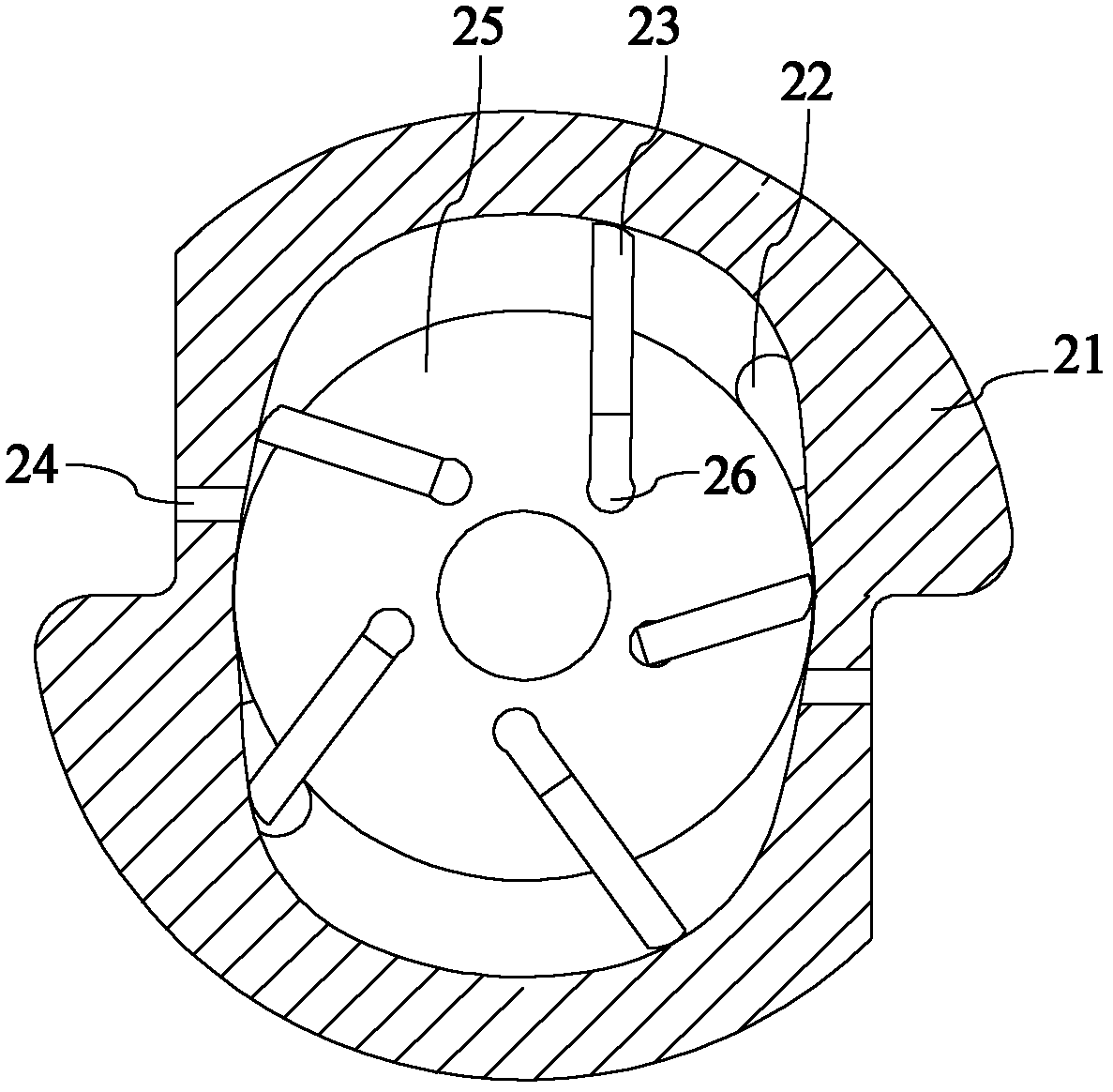
In order to solve the above problems, an arc sealing curve equal to the radius of the rotor is added at the contact between the cylinder and the rotor, and then the combined curve connected with the simple harmonic curve is used as the cylinder profile, which ensures that the minimum distance between the cylinder and the rotor is ensured. The radial part is in surface contact, but due to the unsmooth connection between the sealing curve and the simple harmonic curve, the rotor will produce sudden acceleration changes during operation, resulting in soft impact and noise, which will accelerate the wear of the compressor blades and cylinder

Method used


Image

  • Rotary vane compressor
  • Rotary vane compressor
  • Rotary vane compressor

Examples


Embodiment 1

[0118] The rotary vane compressor in the embodiment is the same as the conventional 96-type rotary vane compressor in structural dimensions, namely: R=33.5mm; r=25.1mm; e=7.2mm; B=3.6mm; cylinder body width Lz= 40mm.

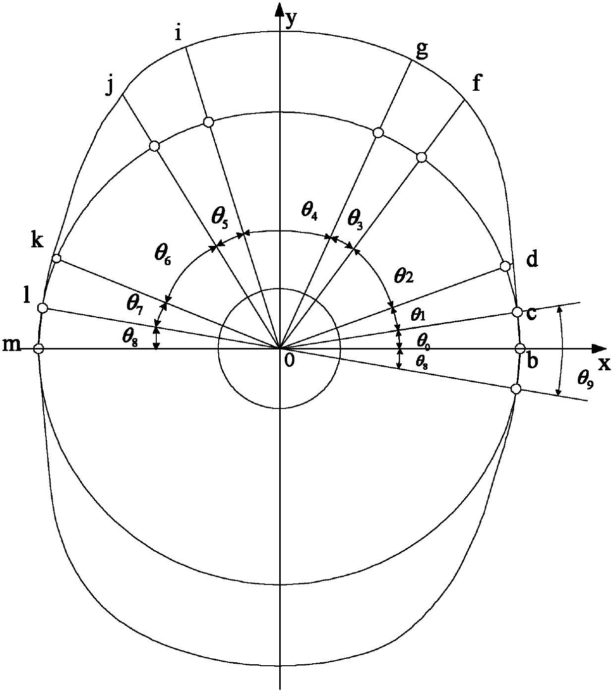
[0119] Pole diameter ρ of cylinder profile line and blade displacement S, pole angle θ and rotor rotation angle The relationship is as follows:

[0120]

[0121] Formula (9)

[0122] Through angle optimization, the corner span values ​​of each segmental motion curve are obtained as follows:

[0123] θ 0 = 1 180 π θ 1 = 17 180 π θ 2 = ...


PUM


Abstract

The embodiment of the invention discloses a rotary vane compressor, which comprises a rotor, a front end cover, a rear end cover, blades and a cylinder body, wherein inner surface shafts of the cylinder body are symmetric; the front end cover and the rear end cover are arranged at the two ends of the cylinder body; the rotor is arranged in the cylinder body; a sliding groove is arranged at a radial eccentric position on the rotor; the blades are arranged in the sliding groove; the rotor profile of the rotor is round; the motion curve of the blades is an extremely approximate function of the cylinder body profile of the cylinder body obtained by the displacement functions of the blades, and Theta is the rotor angle of the rotor; the cylinder body profile of the cylinder body of the rotary vane compressor is obtained by conversion according to the motion curve of the blades; three-order continuousness is ensured by the joints of all segments of the motion curve so as to prevent power impact on the blades. By optimization of angles, the tightness of the contact position between the cylinder body of the compressor and the rotor is ensured, and the air suction capacity and the theoretical exhaust capacity are improved under the condition of unchanged structural size of the compressor.

Description

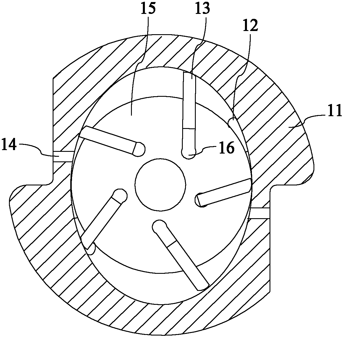
technical field [0001] The invention relates to the field of compressors, more specifically, to a rotary vane compressor. Background technique [0002] Rotary vane compressors have become the mainstream of automotive refrigeration compressors due to their compact structure, small bearing force, stable operation, and simple structure. [0003] Traditional rotary vane compressors, such as figure 1 As shown, the rotary vane compressor includes a cylinder body 11, blades 13, rotor 15 and front and rear end covers, wherein the rotor 15 is arranged inside the cylinder body 11, and its profile is a perfect circle, and the inside of the rotor 15 is radially eccentric There is a chute 16 at the center, and the blade 13 reciprocates in the chute 16; the front and rear end covers are arranged at both ends of the cylinder body 11; the inner surface of the cylinder body 11 is a quasi-ellipse shape), on which there is an exhaust port 14, and the suction port 12 is opened on the end cove...

Claims


Application Information

Patent Timeline
IPC IPC(8): F04C2/344
Inventor 宋立权邹凯
Owner CHONGQING UNIV
Learn More