
Method for increasing horizontal restraint and improving and determining bearing capacity of supporting frame

A technology of horizontal restraint and support frame, applied in the field of support frame, can solve the problems of increasing the corresponding relationship, safety accidents, and inability to determine the added value of critical load, etc.

Inactive Publication Date: 2011-09-14
ZHEJIANG DAHUA CONSTR GROUP
View PDF5 Cites 1 Cited by
  • Summary
  • Abstract
  • Description
  • Claims
  • Application Information

AI Technical Summary

Problems solved by technology

[0002] At present, the support frame used in the construction site is relatively free to set the horizontal constraint. Some do not set it, and the value of the critical load increase cannot be determined if it is set. There is no corresponding relationship between the horizontal constraint and the critical load after the structure is erected. The site is erected based on experience. On the one hand, it causes waste of materials and increases the cost; on the other hand, it causes potential safety hazards, and some even cause major safety accidents

Method used


Image

  • Method for increasing horizontal restraint and improving and determining bearing capacity of supporting frame
  • Method for increasing horizontal restraint and improving and determining bearing capacity of supporting frame
  • Method for increasing horizontal restraint and improving and determining bearing capacity of supporting frame

Examples


Embodiment Construction

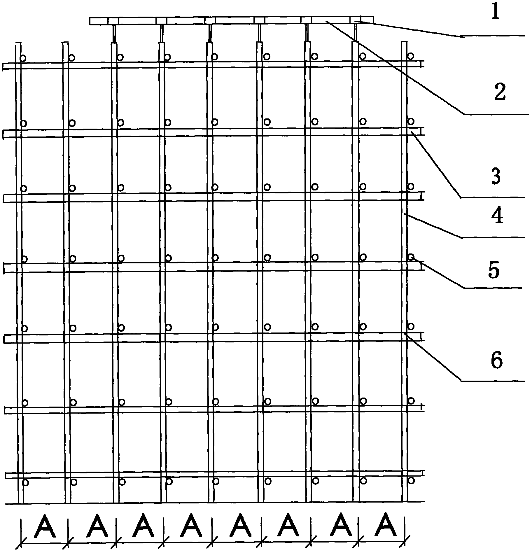
[0014] Such as Figure 1~5 As shown, the support frame adopts a fastener type steel pipe support frame, which includes a vertical steel pipe 4, a longitudinal horizontal rod 3, a horizontal horizontal rod 5, and a malleable cast iron fastener 6; the upper part of the bracket is supported by an adjustable bracket 1 Φ48×3.2 double steel pipes 2. The distance from the upper surface of the adjustable bracket to the bottom surface of the steel pipe of the vertical pole, that is, the height C is 8.2m, and the distance between the axis of the adjacent longitudinal horizontal pole or the adjacent horizontal horizontal pole, that is, the step distance E of the vertical pole is 1.24m, and the vertical pole The longitudinal spacing A of the steel pipes is 0.9m, the horizontal spacing B of the vertical pole steel pipes is 0.9m, and the height D of the sweeping pole is 0.2m.

[0015] The aspect ratio of the support=8.2÷(6×0.9)=1.5; the sweeping rod is the lower cross bar of the support, an...


PUM

PropertyMeasurementUnit
Vertical spacingaaaaaaaaaa
Pitchaaaaaaaaaa

Abstract

The invention relates to a method for increasing horizontal restraint and improving and determining the bearing capacity of a supporting frame. The supporting frame moves eight strides in longitudinal direction, moves six strides in transverse direction and is loaded within a 5-stride*5-stride range; the supporting frame moves two strides to one side in the longitudinal direction outside a loading area and moves one stride to the other side; the supporting frame moves one stride to one side in the transverse direction outside the loading area and moves no stride to the other side; the height of the supporting frame is 8.2 metres (m); step distances of vertical rods are 1.24 m; longitudinal intervals of the vertical rods are 0.9 m; transverse intervals of the vertical rods are 0.9 m; the ratio of height to width of the supporting frame is 1.5; the supporting frame is constructed by steel pipes with the diameter of Phi 48*3.2; an adjustable bracket which supports double steel pipes with the diameter of Phi 48*3.2 serves as a supporting load girder at the upper part of the supporting frame; the bottom of the adjustable bracket is inserted into the vertical rods of the supporting frame for fixation; a distance between an upper surface of the adjustable bracket and the upper surface of the uppermost transverse pipe of the supporting frame is 0.55 m; the adjustable bracket extends out of the vertical rods by 0.3 m; and a horizontal restraint rod is arranged on a counter-force frame at a position which is 5.3 m high. The structure of the supporting frame of a fastener can be economical, reasonable, safe and applicable by increasing the horizontal restraint and improving and determining the bearing capacity of the supporting frame.

Description

technical field [0001] The invention relates to a method for increasing horizontal constraints to improve and determine the bearing capacity of a support frame. The support frame used on a construction site, especially the horizontal constraints such as fastening around the steel pipe support frame of a fastener type to the main structure, can effectively improve the bearing capacity. Background technique [0002] At present, the support frame used in the construction site is relatively free to set the horizontal constraint. Some do not set it, and the value of the critical load increase cannot be determined if it is set. There is no corresponding relationship between the horizontal constraint and the critical load after the structure is erected. The site is erected based on experience. On the one hand, it causes waste of materials and increases the cost; on the other hand, it causes potential safety hazards, and some even cause major safety accidents. Contents of the inven...

Claims


Application Information

Patent Timeline
IPC IPC(8): E04G21/00E04G5/04
Inventor 刘群
Owner ZHEJIANG DAHUA CONSTR GROUP
Learn More