
Method and device for producing fuel algae in continuous U-shaped tube and application thereof

A production method and a production device technology, which are applied in the fields of oil algae production, carbon dioxide treatment, and bio-oil industrial production, can solve the problems of troublesome collection of mature oil algae, low production efficiency of oil algae, and low yield of vegetable oil, and achieve the whole process of oil extraction Controllable, basically controllable oil content, shortened ripening time

Inactive Publication Date: 2011-09-14
叶乃强
View PDF5 Cites 1 Cited by
  • Summary
  • Abstract
  • Description
  • Claims
  • Application Information

AI Technical Summary

Problems solved by technology

In the prior art, the production tests of oil algae are carried out in a planar form (runway-type culture ponds, ponds, natural wetlands, etc.), which occupy a large area, and the capture of carbon dioxide molecules in the air by oil algae is a natural behavior. The disadvantages of slow growth, uncontrollable maturity period, and uncontrollable oil content lead to low production efficiency of oil algae, troublesome collection of mature oil algae, and low yield of extractable vegetable oil

Method used


Image

  • Method and device for producing fuel algae in continuous U-shaped tube and application thereof
  • Method and device for producing fuel algae in continuous U-shaped tube and application thereof
  • Method and device for producing fuel algae in continuous U-shaped tube and application thereof

Examples


Embodiment Construction

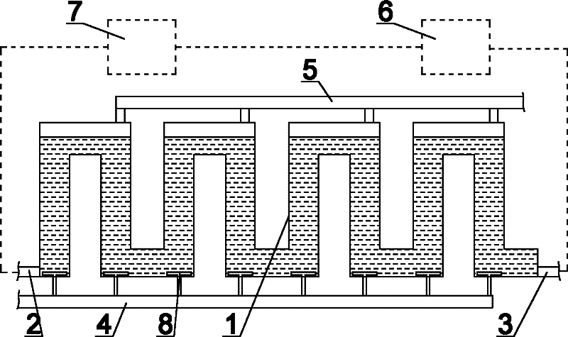
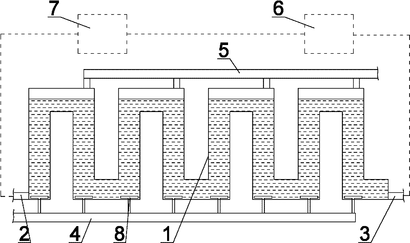
[0023] Embodiments of the invention. Continuous U-tube oil algae production device, such as figure 1 As shown, the U-shaped tube 1 is made of transparent materials such as glass or plastic, and the tops of the U-shaped tubes 1 are connected sequentially to form a continuous channel. The tail end of the tube 1 is provided with a culture solution outlet 3 , a carbon dioxide inlet 4 is installed at the bottom of the U-shaped tube 1 , and a gas collection port 5 is installed at the top of the U-shaped tube 1 .

[0024] In order to realize circular production, the culture solution outlet 3 of the continuous U-shaped pipe 1 is connected to the algae separation tank 6 through a pipeline, and the culture solution of the oil and algae separation tank 6 enters the feeding tank 7 through the pipeline, and the feeding tank 7 is connected to the continuous U-shaped tube 1 The culture medium import 2.

[0025] The carbon dioxide gas inlet 4 at the bottom of the U-shaped pipe 1 is connecte...


PUM

PropertyMeasurementUnit
diameteraaaaaaaaaa
heightaaaaaaaaaa
diameteraaaaaaaaaa

Abstract

The invention discloses a method and a device for producing fuel algae in a continuous U-shaped tube and application thereof. The method is characterized by comprising the following steps of: persistently feeding seeds of the fuel algae and culture solution into the continuous U-shaped tube, wherein the tops of the U-shaped tube are sequentially connected to form a continuous channel, and a gas collection port is formed on the tops of the U-shaped tube and is used for collecting gas so as to reduce the internal pressure of the tube; and adding carbon dioxide gas into the U-shaped tube through a carbon dioxide inlet at the bottom of the U-shaped tube to promote the growth of the fuel algae, and driving the fuel algae to roll and move in the U-shaped tube by persistently injecting the culture solution with the seeds of the fuel algae until the fuel algae are mature. The invention has the advantages that: the continuous channel is formed in the U-shaped tube, the adding, culture and collection of the fuel algae are circularly operated, and the interference of miscellaneous algae is also excluded; CO2 is fed into the U-shaped tube, so that CO2 molecules are fully captured by the fuel algae, and the growth of the fuel algae is promoted; the illumination time and the illumination intensity can be controlled, so that the optimal growth environment of the oil algae is created, and the full-range controllability of the culture of the fuel algae is realized; and the yield of the fuel algae is high.

Description

technical field [0001] The invention relates to a continuous U-shaped tube oil algae production method and device and application thereof, belonging to the fields of oil algae production, carbon dioxide treatment, and bio-oil industrial production. Background technique [0002] In recent years, some biological experts at home and abroad have found that oil algae can absorb, decompose, and convert carbon dioxide into oxygen during the process of reproduction and growth, and fix carbon in the body to form oil. Compared with other biodiesel raw materials, oil algae has oily High yield (20-50% oil content) and short growth period (the young oil algae seeds only need 7-10 days to mature under the condition of sufficient supply of carbon dioxide), abundant resources (more than 20 kinds of alternatives have been found at present) It can be used as the main raw material of biodiesel because of its characteristics such as the cultivated oil algae species. In the prior art, the produ...

Claims


Application Information

Patent Timeline
Patent Type & Authority Applications(China)
IPC IPC(8): C12N1/12C12M1/00B01D53/84B01D53/62C12R1/89
CPCC12M29/06C12M21/02C12M23/36Y02C10/02Y02C10/04Y02C20/40
Inventor 叶乃强
Owner 叶乃强
Learn More