
Connecting and clamping device for conductive body, particularly conductive body with wire nose

A technology of clamping device and conductor, which is applied in the direction of clamping/spring connection, etc., can solve the problems of occupying space and occupying a lot of space, and achieve the effect of optimizing the installation space

Inactive Publication Date: 2011-09-07
SIEMENS AG
View PDF0 Cites 1 Cited by
  • Summary
  • Abstract
  • Description
  • Claims
  • Application Information

AI Technical Summary

Problems solved by technology

The disadvantage is that this superposition takes up a lot of space, since the clamps have to be arranged staggered
Particularly space-consuming due to the mirrored arrangement of these opposite clamps

Method used


Image

  • Connecting and clamping device for conductive body, particularly conductive body with wire nose
  • Connecting and clamping device for conductive body, particularly conductive body with wire nose
  • Connecting and clamping device for conductive body, particularly conductive body with wire nose

Examples


Embodiment Construction

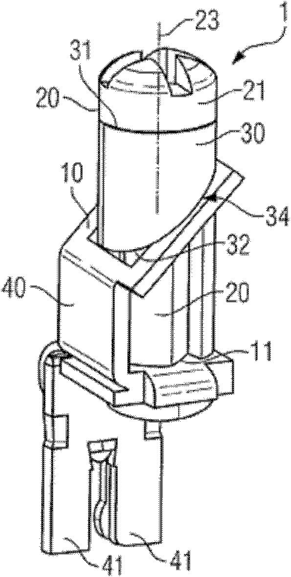
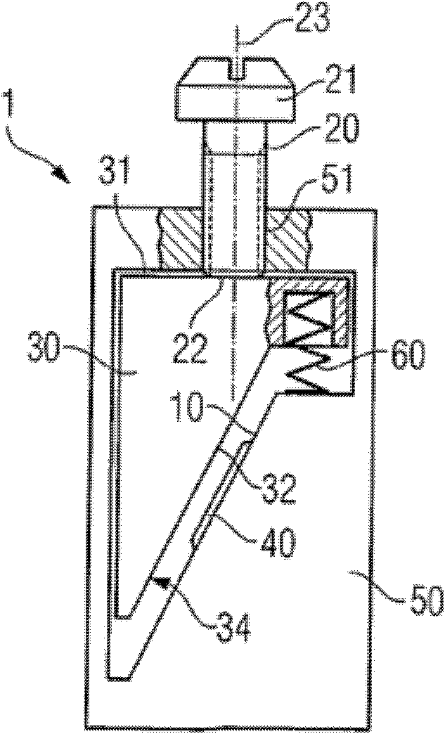
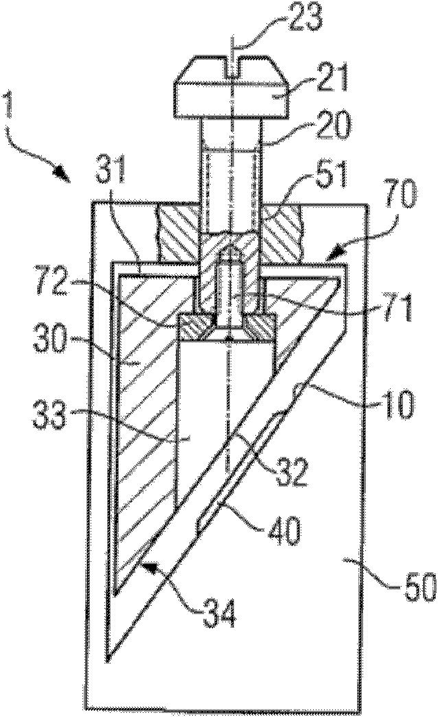
[0032] attached figure 1 Shown is a connection clamping device 1 comprising a clamping surface 10 , a clamping element 20 and a clamping part 30 . The clamping surface 10 is oblique at an angle to the longitudinal axis 23 of the clamping element 20 , which here is a clamping screw. The clamping element 20 is screwed into a threaded hole 11 on the clamping surface 10 . The clip 30 is inserted on the clamping element 20 , that is to say on the thread of the clamping screw. The clamping piece 30 thus has a hollow cylindrical shape, wherein the end face 31 of the clamping part 30 facing the clamping screw head 21 is straight and the end face 32 of the clamping part 30 facing the clamping surface 10 is inclined. The end face 32 of the clip part 30 facing the clamping face 10 can serve as a contact area 34 for an electrical conductor or a wire lug. The clamping surface 10 has at least one region oblique to the longitudinal axis 23 of the clamping element 20 . By means of the cla...


PUM


Abstract

The invention relates to a connecting and clamping device (1) used for an electric wire, particularly for an electric wire with a wire nose at the end. The connecting and clamping device comprises at least one clamping surface (10), at least one clamping component (20), especially a clamping screw, at least one clamping piece (30) which is movable installed, wherein the at least one clamping surface (10) oblique crosses with the at least one clamping component (20), especially the longitudinal axis (23) of the clamping screw, region by region. The invention also relates to electrical equipment with the connecting and clamping device (1).

Description

technical field [0001] The invention relates to a connection and clamping device for conductors, especially suitable for an electric wire with a lug at the end, comprising: at least one clamping surface; at least one clamping element, especially a clamping screw; and Including at least one removable mounting clip. The invention also relates to an electrical device with such a connection clamp. Background technique [0002] In order to avoid unraveling of the wire ends when using flexible electrical conductors (such as stranded wires) and thus to ensure a good, reliable contact between the wire and an electrical device, the wire end is usually first closed off with a so-called lug. This lug is then clamped in the connection clamp of the electrical system. [0003] A number of various forms of lugs are known, such as elbow lugs, ring lugs, tubular lugs, solder lugs, fork lugs and needle lugs. The lug can be used to mechanically and electrically connect a stripped wire end, ...

Claims


Application Information

Patent Timeline
Patent Type & Authority Applications(China)
IPC IPC(8): H01R4/28H01R4/30
Inventor 沃尔夫冈·霍尔默
Owner SIEMENS AG
Learn More