
Method for realizing three-dimensional coherent imaging by ground penetrating radar under near field condition

A ground-penetrating radar and coherent imaging technology, which is applied in the directions of radio wave reflection/re-radiation, utilization of re-radiation, measurement devices, etc., can solve problems such as difficult near-field conditions

Inactive Publication Date: 2011-09-07
SHAANXI YANCHANG PETROLEUM GRP +1
View PDF1 Cites 24 Cited by
  • Summary
  • Abstract
  • Description
  • Claims
  • Application Information

AI Technical Summary

Problems solved by technology

[0004] In the chirp system, near-field imaging radar must use coherent imaging technology to obtain high-resolution radar images. However, current coherent imaging technologies such as chirp scaling and wavenumber domain are designed for far-field models. conditions, some approximation, or interpolation is a limitation of the support domain, making it difficult to apply these algorithms to near-field conditions

Method used


Image

  • Method for realizing three-dimensional coherent imaging by ground penetrating radar under near field condition
  • Method for realizing three-dimensional coherent imaging by ground penetrating radar under near field condition
  • Method for realizing three-dimensional coherent imaging by ground penetrating radar under near field condition

Examples


Embodiment Construction

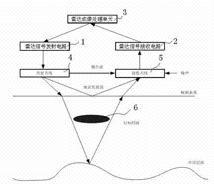
[0019] refer to figure 1 , like a traditional radar system, includes a radar signal transmitting circuit 1, a radar signal receiving circuit 2 and a radar imaging processing unit 3, and transmits radar waves to the target or receives the reflected signal of the target through the radar antenna (transmitting antenna 4 and receiving antenna 5), In the present invention, in the detection and imaging area 6 of the buried oil pipeline, the maximum detection depth is required to be 3.5 meters, that is, the distance difference between the target local oscillator and the target echo is about 7 meters, so the intermediate frequency of the echo is received The bandwidth is (the earth permittivity at this time is estimated by 9):

[0020]

[0021] In the above formula is the bandwidth of the received signal, is the modulation frequency of the transmitted chirp signal, is the speed of light, The dielectric constant of the earth, is the maximum operating distance.

[0022] Th...


PUM


Abstract

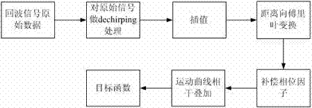
The invention belongs to the technical field of radar imaging, and particularly discloses a method for realizing three-dimensional coherent imaging by a ground penetrating radar under near field condition. The method is characterized by comprising the following steps of: 1) transmitting radar waves to a target at transmission frequency f, and performing difference frequency processing on a target echo signal received by the radar and a reference signal to obtain a difference frequency processed echo signal; 2) interpolating the difference frequency processed echo signal, and performing range direction compression; 3) dividing an imaging area into grids, and calculating delays of each grid point or pixel point, delayed by the radar, in the imaging area at each azimuthal position; 4) performing phase compensation on echoes of corresponding points according to the calculated delays; 5) performing coherence addition on each pixel point to obtain an addition result which is a value of the pixel point; and 6) traversing the whole imaging area by adopting the steps 4) and 5) to obtain an imaging function, and finishing the reconstruction of an image. In the method for realizing the three-dimensional coherent imaging by the ground penetrating radar under the near field condition, the three-dimensional imaging is performed on a near field target area, and relatively higher resolution is ensured.

Description

technical field [0001] The invention belongs to the technical field of radar imaging, in particular to a three-dimensional coherent imaging method of ground penetrating radar under near-field conditions. The invention is suitable for the back-projection algorithm of near-field target region imaging. Background technique [0002] In recent years, radar near-field detection technology has gradually become one of the hot issues in radar application research due to demand traction. Near-field radar can be applied to different occasions, such as; through-wall detection, mine detection, road non-destructive testing, underground bunker detection and archaeological digs. At present, the radar works in the near-field mode, basically focusing on detection. [0003] Most foreign and domestic ground penetrating radar products use the signal form without carrier shock. The ground penetrating radar without carrier shock has the advantage of simple system. Generally, only shock signal ge...

Claims


Application Information

Patent Timeline
Patent Type & Authority Applications(China)
IPC IPC(8): G01S13/89G01S7/41
Inventor 王香增高瑞民刘立李建东王成达唐禹张永强邢孟道李辉张世君刘杰何飞
Owner SHAANXI YANCHANG PETROLEUM GRP
Learn More