Measuring device for measuring capacitance in parallel capacitor bank

A capacitor bank and testing device technology, which is applied in measuring devices, measuring resistance/reactance/impedance, measuring electrical variables, etc., can solve the problems that the balance cannot reach the optimal configuration, the workload of on-site testing is large, and the calculation time is long. Achieve the effect of avoiding the possibility of error, fast calculation method and simple operation

Inactive Publication Date: 2011-09-07
WUXI POWER SUPPLY JIANGSU PROVINCE ELECTRIC POWER
View PDF5 Cites 13 Cited by
  • Summary
  • Abstract
  • Description
  • Claims
  • Application Information

AI Technical Summary

Problems solved by technology

[0003] In the field, the capacitors are connected in parallel in groups, so the general capacitance meter needs to remove the lead wires before measuring, the workload is heavy, and it is easy to cause wiring errors
[0004] There are many capacitors in the capacitor bank, and the on-site testing workload is heavy. At present, the calculation of capacitance balance configuration is performed manually by personnel. The process is cumbersome, the calculation time is long, and the balance often cannot reach the optimal configuration.

Method used


Image

  • Measuring device for measuring capacitance in parallel capacitor bank
  • Measuring device for measuring capacitance in parallel capacitor bank
  • Measuring device for measuring capacitance in parallel capacitor bank

Examples


Embodiment Construction

[0019] The present invention will be further described below in conjunction with specific drawings and embodiments.

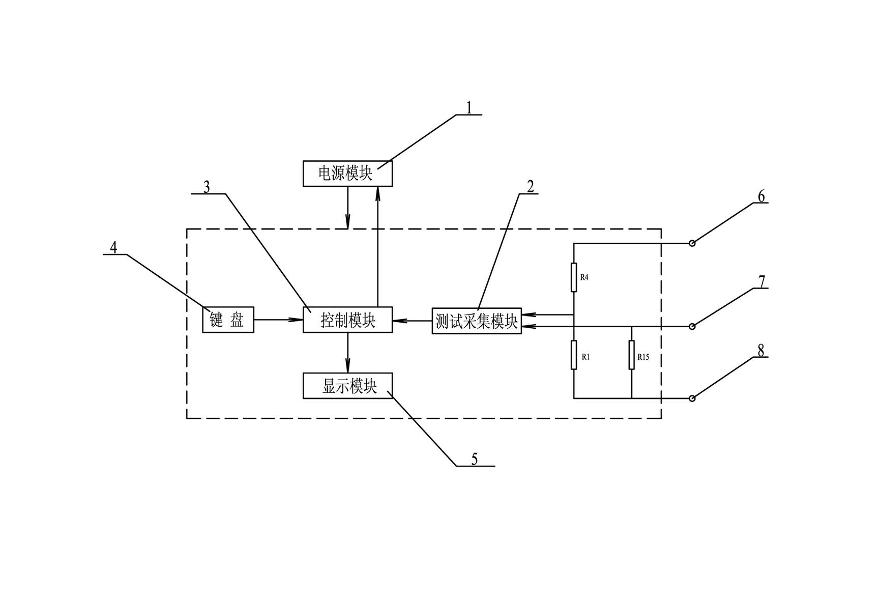
[0020] Such as figure 1 As shown: the present invention includes a power supply module 1 , a test collection module 2 , a control module 3 , a keyboard 4 , a display module 5 , a first test terminal 6 , a current input terminal 7 and a second test terminal 8 .

[0021] Such as figure 1 Shown: the test device includes a test collection module 2, the test collection module 2 is used to collect the current value and the voltage value of the capacitor to be tested, and the input terminal of the test collection module 2 includes a first test terminal 6 and a current input terminal 7 And the second test terminal 8, the first test terminal 6 and the second test terminal 8 are used to measure the voltage value at both ends of the capacitor to be tested, and the first test terminal 6 and the second test terminal 8 pass through the voltage dividing resistor R4 and the v...


PUM


Abstract

The invention relates to a testing device for measuring capacitance in a parallel capacitor bank. According to the technical scheme provided by the invention, the testing device for measuring capacitance in the parallel capacitor bank comprises a testing and collecting device, wherein the output end of the testing and collecting module is connected with the input end of a control module; the power ends of the testing and collecting module and the control module are respectively and electrically connected with a power output end of a power module; the testing and collecting module measures the current value of capacitance to be tested and the voltage value at two ends of capacitance to be tested, and inputs the current value and the voltage value in the control module after the current value and the voltage value are converted; and the control module obtains the active power value of the capacitance to be tested according to the treated and measured current value and the voltage value, and stores and outputs the capacitance value of the capacitance to be tested after treatment according to the active power of the capacitance to be tested, the measured current value and the voltage value. The testing device provided by the invention has the advantages of simple and compact structure, wide application range, high measuring accuracy, safety and reliability, and is convenient to install and use.

Description

technical field [0001] The present invention relates to a test device, especially a test device for measuring the capacitance in a parallel capacitor bank, in particular to a test device which can be used for testing the capacitance in a parallel capacitor bank and can simultaneously perform three-phase capacitor bank balance A testing device belongs to the technical field of capacitance measurement. Background technique [0002] In order to reduce the reactive power loss in the power system, the method of connecting capacitor banks in parallel is usually used to improve the power factor. In practical application, the accident rate of capacitor compensation device is relatively high, which is related to its working state. The characteristics of the working state of the capacitor device can be summarized in twelve words: high field strength, full load, frequency switching, and many attachments. The four aspects contained in these twelve words are not conducive to the reliabi...

Claims


Application Information

Patent Timeline
Patent Type & Authority Applications(China)
IPC IPC(8): G01R27/26G01R19/02
Inventor 黄芬周芸赵胤缪中章李炯田栋
Owner WUXI POWER SUPPLY JIANGSU PROVINCE ELECTRIC POWER
Why Eureka
Try Eureka