
Die for strips of winding pipes

A technology for winding pipes and strips, which is used in the field of molds for manufacturing plastic-steel winding pipes and strips, can solve problems such as product defects and unreasonable flow channel structures, and achieve the effects of sufficient material supply, sufficient material supply, and complete structural formation.

Active Publication Date: 2011-09-07
HUAHAN SCI & TECH
View PDF9 Cites 0 Cited by
  • Summary
  • Abstract
  • Description
  • Claims
  • Application Information

AI Technical Summary

Problems solved by technology

[0005] The technical problem to be solved by the present invention is to provide a winding pipe strip mold to overcome the product defects caused by the unreasonable flow channel structure of the existing winding pipe strip mold

Method used


Image

  • Die for strips of winding pipes
  • Die for strips of winding pipes
  • Die for strips of winding pipes

Examples


Embodiment 1

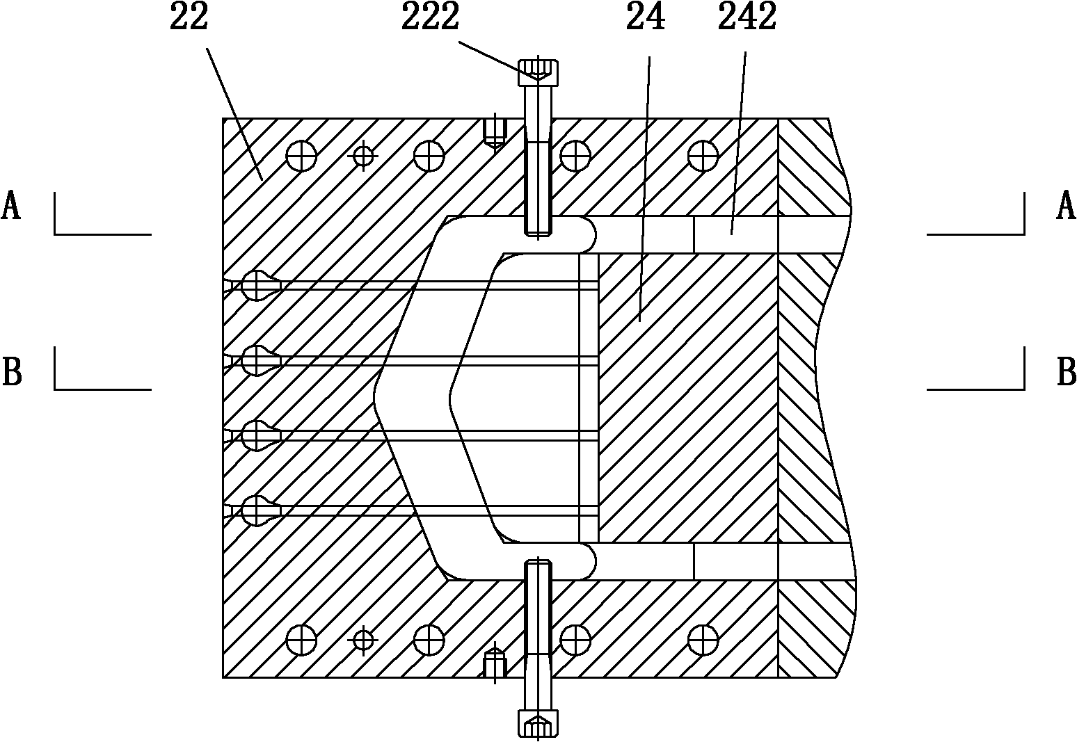
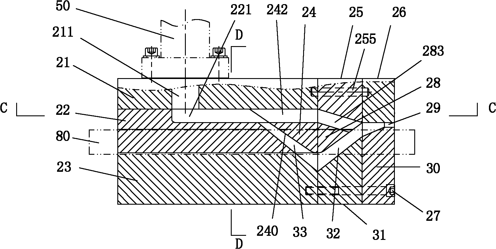
[0033] like Figure 2 to Figure 7 As shown, the coiled pipe strip mold of the present invention includes an upper cover plate 21, a core plate, a runner plate 24, a transition plate and a discharge plate, and the core plate, the transition plate and the discharge plate are along the feed direction of the mold steel band 80 Connect sequentially.

[0034] The upper cover 21 includes a molten plastic injection port 211 connected to the molten plastic feed pipe 50 .

[0035] The core plate includes an upper core plate 22 and a lower core plate 23 that are connected up and down. The upper core plate 22 is connected with the upper cover plate 21 up and down. The upper core plate 22 includes a runner groove 221 located below the molten plastic injection port 211 .

[0036] The core plate includes core plate steel strip guide holes 100 arranged at the same level in parallel intervals, a runner lower slope 200 inclined downward along the mold steel strip feeding direction, and an inn...

Embodiment 2

[0058] like Figure 8 As shown, the coiled pipe strip mold of the present invention includes an upper cover plate 21, a core plate, a runner plate 24 and a discharge plate. The difference between this embodiment and Embodiment 1 is that the transition plate is cancelled, and the discharge plate is directly connected to the discharge end of the core plate. The tape is compounded with molten plastic only once. One end of the auxiliary runner channel 242 arranged on both sides of the runner plate 24 communicates with the runner groove 221 , and the other end communicates with the cavity of the overlapping edge arranged on the discharge plate.

Embodiment 3

[0060] On the mold core of the existing coiled pipe strip mold adopting the formwork structure, the auxiliary runners located on both sides of the main flow channel and connected to the groove of the flow channel and the cavity of the lap edge of the strip can also be realized. .


PUM


Abstract

The invention relates to a die for strips of winding pipes, and the die provided by the invention comprises a molten plastic injection port connected with a molten plastic feed pipe, a strip plastic wall die cavity, overlap edge die cavities arranged on two sides of the strip plastic wall die cavity and a main flow passage for communicating the molten plastic injection port with the strip plasticwall die cavity, as well as auxiliary flow passages, wherein the auxiliary flow passages are arranged on two sides of the main flow passage and communicated with the molten plastic injection port andthe overlap edge die cavities. The special auxiliary flow passage for material supply for strip overlap edges is arranged, thereby ensuring the sufficient material supply for the strip overlap edges and the complete structure shaping; and the material supply for the strip overlap edges does not occupy molten plastic of the main flow passage of the strip plastic wall die cavity, thereby ensuring the structural mass of the strip overlap edges, simultaneously ensuring the sufficient material supply for strip plastic walls and ensuring the structural mass of strip plastic walls.

Description

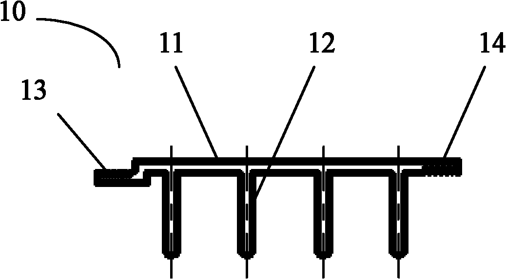
technical field [0001] The invention relates to a mold for manufacturing plastic-steel winding pipe strips. Background technique [0002] Plastic-steel spiral wound pipe is a new type of pipe that replaces traditional cement pipes, steel pipes, etc., and has been widely used in urban underground pipe networks. To manufacture the plastic-steel spiral wound pipe, it is first necessary to compound the reinforced steel strip and plastic to form a wound pipe strip 10, and then use a special spiral winding equipment to wind and connect the strips to make a plastic-steel spirally wound pipe product. [0003] like figure 1 As shown, the molten plastic material and the steel belt are composited into a cross-sectional structure through a special mold, including a plastic wall 11, a reinforcing rib 12 erected on one side of the plastic wall 11, and overlapping structures 13 and 14 arranged on both sides of the plastic wall 11 The winding pipe strip 10. [0004] Existing winding pipe...

Claims


Application Information

Patent Timeline
IPC IPC(8): B29C45/26
Inventor 郑能欢李文俊
Owner HUAHAN SCI & TECH
Learn More