
Method for predicting surface roughness in single-point diamond turning

A single-point diamond and surface roughness technology, which is applied in metal processing, stone processing equipment, stone processing tools, etc., can solve the problems of large errors in surface roughness prediction methods and achieve the effect of improving prediction accuracy

Inactive Publication Date: 2011-09-07
HARBIN INST OF TECH
View PDF4 Cites 10 Cited by
  • Summary
  • Abstract
  • Description
  • Claims
  • Application Information

AI Technical Summary

Problems solved by technology

[0008] In order to solve the problem that the existing surface roughness prediction method has large errors, the present invention further proposes a method for predicting surface roughness in single-point diamond turning

Method used


Image

  • Method for predicting surface roughness in single-point diamond turning
  • Method for predicting surface roughness in single-point diamond turning
  • Method for predicting surface roughness in single-point diamond turning

Examples


specific Embodiment approach 1

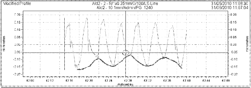
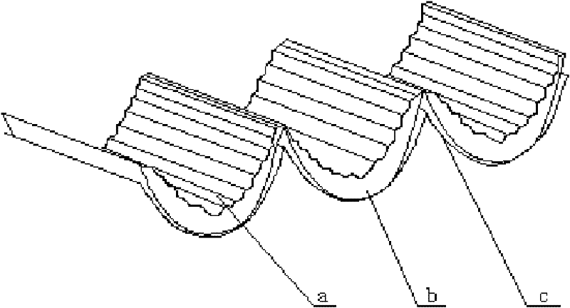
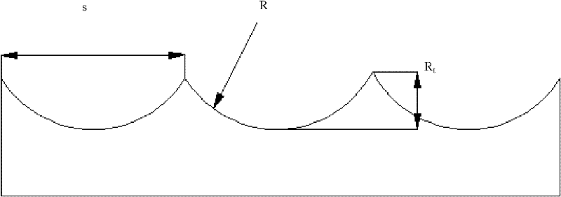
[0023] Specific implementation mode one: as Figure 1-10 As shown, the establishment steps of a single-point diamond turning surface roughness prediction method described in this embodiment are as follows:

[0024] Step 1. Select a typical workpiece material to be tested, design an experimental plan by changing the feed speed, spindle speed and back cutting amount, and conduct a pre-single-point diamond cutting experiment on an ultra-precision machine tool;

[0025] Step 2, using a stylus profiler to predict the surface profile curve of a typical workpiece to be measured;

[0026] Step 3, extracting the amplitude information of the relative vibration between the tool and the workpiece during the machining process from the detection results of the processed surface, the amplitude information of the relative vibration between the tool and the workpiece is obtained by the following method:

[0027] Step 3 (1), according to the detected surface contour curve and data, establish t...

specific Embodiment approach 2

[0036] Under the condition that the rotation speed is 1000r / min, the back cutting amount is 2μm, and the feed speed is 25mm / min, for NiP, the relative vibration amplitude information is extracted 5nm, for Cu, to extract relative vibration amplitude information 15nm, through Calculation of equivalent relative vibration;

[0037] Such as Figure 5-7 As shown, the expansion ratio SP is calculated. Under this processing condition, the expansion ratio SP of NiP is 1.3, and the expansion ratio SP of Cu is 0.65. Calculate the contour curve of the processed surface after the expansion effect occurs;

[0038] Using matlab software, the contour curve of the machined surface after the expansion effect occurs and the equivalent relative vibration are superimposed and the data is processed and calculated to obtain the predicted results. The comparison between the predicted results and the actual results is as follows Figure 8 and Figure 9 ;

[0039] Such as Figure 8-9 As shown,...


PUM


Abstract

The invention relates to a method for predicting surface roughness, in particular to a method for predicting surface roughness in single-point diamond turning. The method solves the problem that the conventional method for predicting the surface roughness has high predication error. The method comprises the following steps of: extracting amplitude information of relative vibration between a cutter and a workpiece in the processing process from the detection result of a processed surface, establishing corresponding relationships between the main shaft revolving speed and the material property and between the relative vibration and the expansion effect, calculating a profile curve of the processed surface after the expansion effect happens, finding the corresponding equivalent amplitude according to the specific processing material and the main shaft revolving speed so as to obtain equivalent relative vibration between the cutter and the workpiece, superposing the equivalent relative vibration and the profile curve of the processed surface after the expansion effect happens to obtain a new surface profile curve, performing data processing on the new curve and calculating the surface roughness. The method is used for predicting the surface roughness in the single-point diamond turning.

Description

technical field [0001] The invention relates to a method for predicting surface roughness, in particular to a method for predicting surface roughness in single-point diamond turning. Background technique [0002] Single-point diamond turning generally adopts small depth of cut, low feed and high speed to ensure nano-scale surface roughness, but the mechanism of material removal and surface formation during processing is very complicated. At present, in single-point diamond turning, the surface In the research of roughness prediction, the basic idea of ​​establishing a prediction method for surface roughness based on cutting theory is to superimpose the theoretical surface roughness and the relative vibration between the tool and the workpiece under certain assumptions. The existing prediction methods have the following problems : [0003] 1. The relative vibration between the tool and the workpiece is predicted when the machine tool is idling and not cutting, so it cannot t...

Claims


Application Information

Patent Timeline
Patent Type & Authority Applications(China)
IPC IPC(8): B28D1/16G06F17/50B23Q15/12
Inventor 陈俊云赵清亮罗健
Owner HARBIN INST OF TECH
Learn More